VPI WIRELESS HDMI EXTENDER
Side Panel
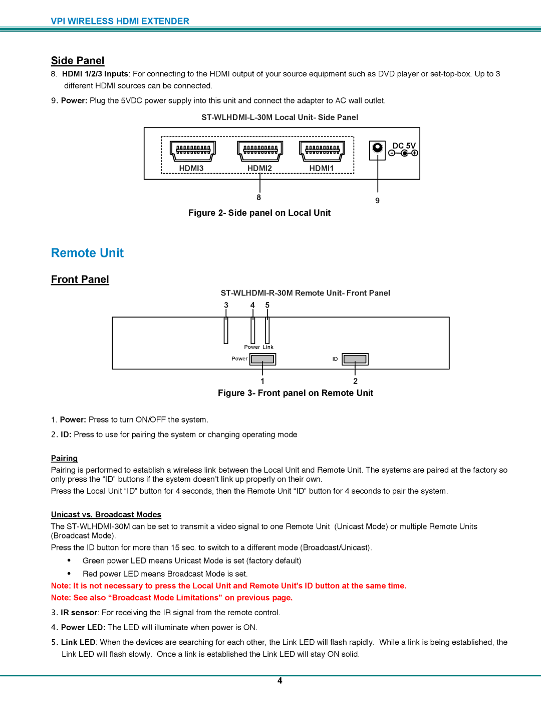
8.HDMI 1/2/3 Inputs: For connecting to the HDMI output of your source equipment such as DVD player or
9.Power: Plug the 5VDC power supply into this unit and connect the adapter to AC wall outlet.
DC 5V
![]()
![]()
HDMI3 HDMI2 HDMI1
8 | 9 |
|
Figure 2- Side panel on Local Unit
Remote Unit
Front Panel
ST-WLHDMI-R-30M Remote Unit- Front Panel
3 | 4 | 5 |
Power Link |
|
Power | ID |
12
Figure 3- Front panel on Remote Unit
1.Power: Press to turn ON/OFF the system.
2.ID: Press to use for pairing the system or changing operating mode
Pairing
Pairing is performed to establish a wireless link between the Local Unit and Remote Unit. The systems are paired at the factory so only press the “ID” buttons if the system doesn’t link up properly on their own.
Press the Local Unit “ID” button for 4 seconds, then the Remote Unit “ID” button for 4 seconds to pair the system.
Unicast vs. Broadcast Modes
The
Press the ID button for more than 15 sec. to switch to a different mode (Broadcast/Unicast).
•Green power LED means Unicast Mode is set (factory default)
•Red power LED means Broadcast Mode is set.
Note: It is not necessary to press the Local Unit and Remote Unit's ID button at the same time.
Note: See also “Broadcast Mode Limitations” on previous page.
3.IR sensor: For receiving the IR signal from the remote control.
4.Power LED: The LED will illuminate when power is ON.
5.Link LED: When the devices are searching for each other, the Link LED will flash rapidly. While a link is being established, the Link LED will flash slowly. Once a link is established the Link LED will stay ON solid.
4
