Front View
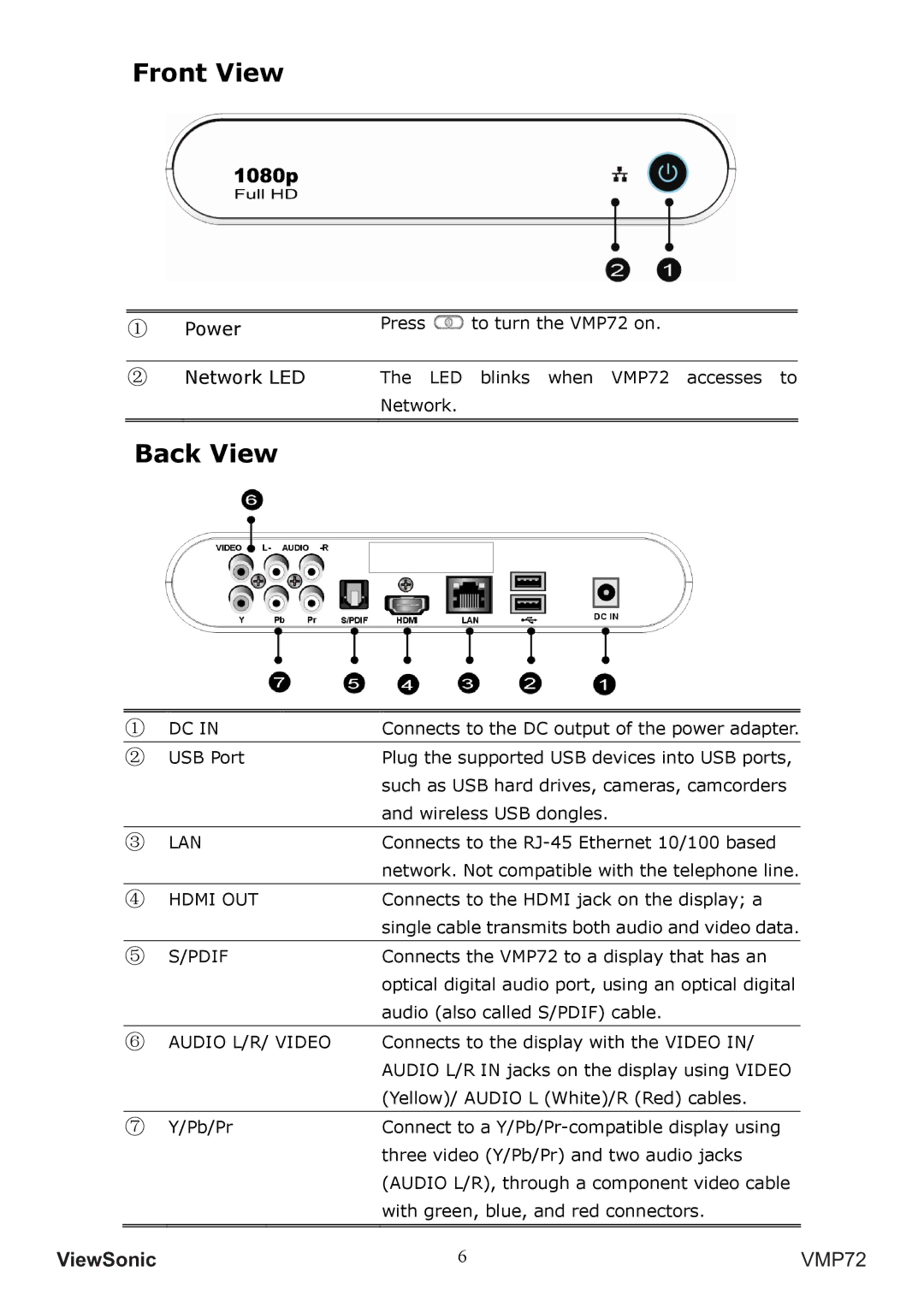
① | Power | Press to turn the VMP72 on. |
②Network LED The LED blinks when VMP72 accesses to Network.
Back View
① | DC IN | Connects to the DC output of the power adapter. |
|
|
|
② | USB Port | Plug the supported USB devices into USB ports, |
|
| such as USB hard drives, cameras, camcorders |
|
| and wireless USB dongles. |
|
|
|
③ | LAN | Connects to the |
|
| network. Not compatible with the telephone line. |
|
|
|
④ | HDMI OUT | Connects to the HDMI jack on the display; a |
|
| single cable transmits both audio and video data. |
|
|
|
⑤ | S/PDIF | Connects the VMP72 to a display that has an |
|
| optical digital audio port, using an optical digital |
|
| audio (also called S/PDIF) cable. |
|
|
|
⑥ | AUDIO L/R/ VIDEO | Connects to the display with the VIDEO IN/ |
|
| AUDIO L/R IN jacks on the display using VIDEO |
|
| (Yellow)/ AUDIO L (White)/R (Red) cables. |
|
|
|
⑦ | Y/Pb/Pr | Connect to a |
|
| three video (Y/Pb/Pr) and two audio jacks |
|
| (AUDIO L/R), through a component video cable |
|
| with green, blue, and red connectors. |
|
|
|
|
|
|
9LHZ6RQLF | 6 | VMP72 |