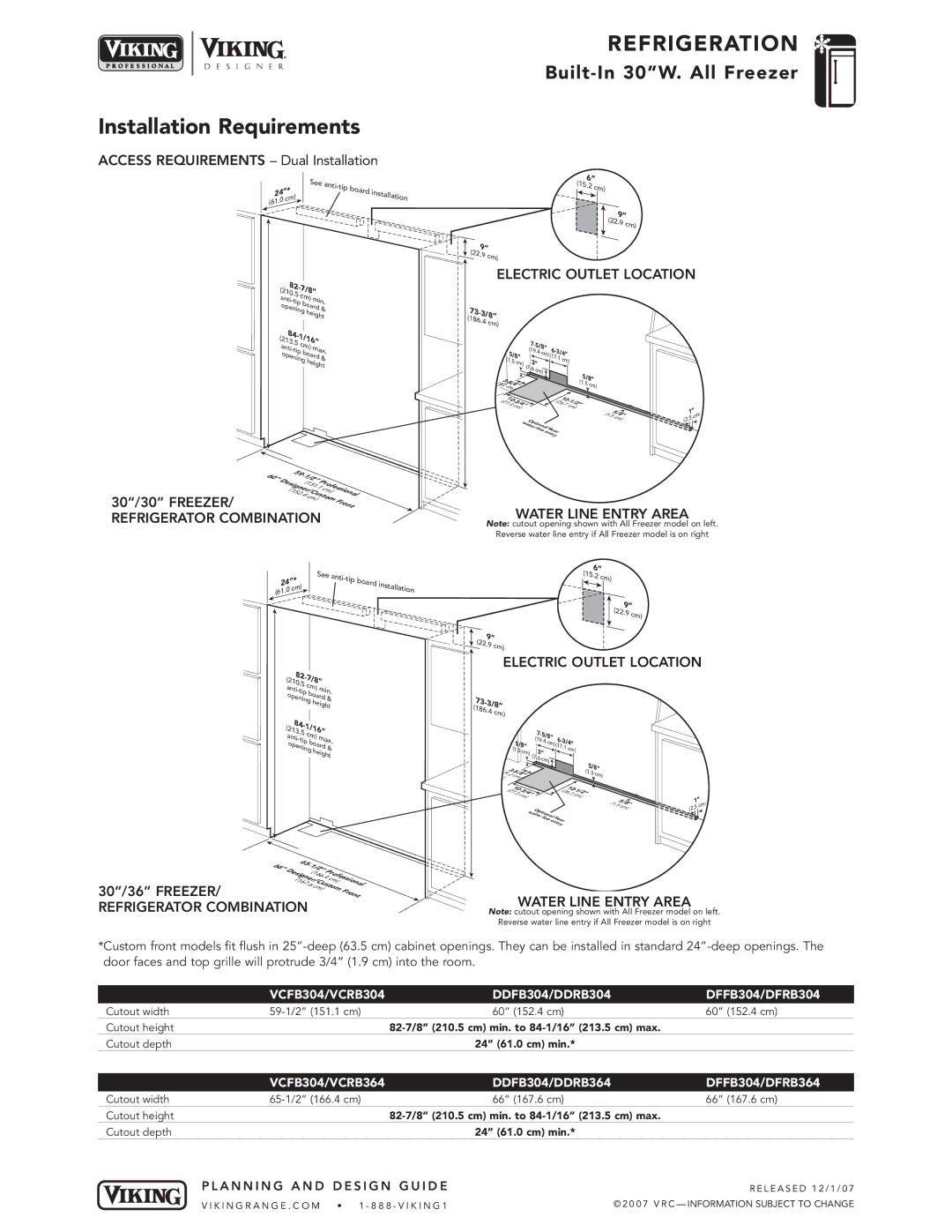
Installation Requirements

ACCESS REQUIREMENTS – Dual Installation


See


anti-tip


cm)

board

installation

24”*


(61

.0


REFRIGERATION

Built-In 30”W. All Freezer


6”


(15.2

cm)


9”


(22.9

cm)

9”


(22.

9 cm)


ELECTRIC OUTLET LOCATION

(21

82-

7/8”


0.5


cm)


anti-

min.


tip


board

&

opening


height

84-


1/16”


(213.5


anti-

cm)

max.

tip


board

&

opening


height


60”

59-


1/2”


Designer/

C


cm)


(152


Profession


(151

.1


30”/30” FREEZER/


.4

cm)ustom


al


Front

73-3/8”


(186.4

cm)


7-


5/8”


6-


(19.4


5/8”


cm)(

3/4”


17.1

cm)


(1.5

cm)

(7.


3”


6

cm)


5/8”


3-


(9.

5/8”


(1.5

cm)


2


cm)


10-


(

10-


(27.

3/4”


1/


26.


2


3


7c


cm)


m)


Op


watertional

floor


line


entry


1.5/8”

5cm)(

1”

)

.5 cm

(2


REFRIGERATOR COMBINATION

WATER LINE ENTRY AREA

Note: cutout opening shown with All Freezer model on left.

Reverse water line entry if All Freezer model is on right


See


24”*

anti-tip

board


(61

.0

cm)


ins

tallation


6”


(15.2


cm)


9”


(22.9

cm)

9”


(22.

9 cm)


ELECTRIC OUTLET LOCATION

82-

7/8”


(210.


5 c


anti-


m)

min.

tip


board

&

opening


height

84-


1/16”


(213.5


anti-

cm)

max.

ope

tip


board

&


ning


height


73-3/8”


(186.4

cm)


7-


5/8”

6-


(19.4


5


cm)

3/4”


/8”


(17.1

cm)


(1.5

cm)

(7.


3”


6 c


m)


5/8”


(9

3-


.2


8”


(1.5 c


cm)


m)


10-


(

10-


(27.3 3/4”


26.7


2”


cm)


cm)


O


watpt


er

ional


line

floor


ent

ry


1.8”

5cm)( 5/

1”

)

.5 cm

(2


66”


65-


Desi


1/2”

P


(166


(167


r/C


rofession


gne


.4

c


m)


30”/36” FREEZER/


.6


usto


al


cm)


m

Front


REFRIGERATOR COMBINATION

WATER LINE ENTRY AREA

Note: cutout opening shown with All Freezer model on left.

Reverse water line entry if All Freezer model is on right

*Custom front models fit flush in 25”-deep (63.5 cm) cabinet openings. They can be installed in standard 24”-deep openings. The door faces and top grille will protrude 3/4” (1.9 cm) into the room.


VCFB304/VCRB304

DDFB304/DDRB304

DFFB304/DFRB304

Cutout width

59-1/2” (151.1 cm)

60” (152.4 cm)

60” (152.4 cm)

Cutout height


82-7/8” (210.5 cm) min. to 84-1/16” (213.5 cm) max.


Cutout depth


24” (61.0 cm) min.*


VCFB304/VCRB364

DDFB304/DDRB364

DFFB304/DFRB364

Cutout width

65-1/2” (166.4 cm)

66” (167.6 cm)

66” (167.6 cm)

Cutout height

82-7/8” (210.5 cm) min. to 84-1/16” (213.5 cm) max.

Cutout depth


24” (61.0 cm) min.*


P L A N N I N G A N D D E S I G N G U I D E


R E L E A S E D 1 2 / 1 / 0 7


V I K I N G R A N G E . C O M • 1 - 8 8 8 - V I K I N G 1


© 2 0 0 7 V R C — INFORMATION SUBJECT TO CHANGE

Page 7
Image 7
Viking DDFB, DFFB, VCFB specifications Installation Requirements, Refrigerator Combination Water Line Entry Area

DDFB, DFFB, VCFB specifications

Viking VCFB, DDFB, and DFFB are innovative fire suppression systems developed to provide efficient and effective protection against various types of fires. These systems utilize advanced technologies and specific design characteristics that make them suitable for a wide range of applications, from industrial facilities to commercial buildings.

The Viking VCFB (Valve Controlled Foam System) is primarily designed for large-scale applications where fire risks are significant. One of its main features is the automatic activation of the foam system, which delivers a highly effective foam blanket over a fire. This foam not only suppresses flames but also prevents reignition and helps cool the fire's surface. A key component of the VCFB is its control valve, which is engineered to release the foam based on predetermined fire conditions, ensuring a timely response.

On the other hand, the Viking DDFB (Deluge Dry Foam System) is renowned for its versatility. This system is ideal for environments that face both liquid and solid fire hazards. The DDFB uses dry foam, which is less prone to breakdown and offers superior insulation against heat. Its design allows for wide coverage areas while maintaining a lower water requirement, which is essential in environments where water damage is a concern.

The Viking DFFB (Deluge Foam System) operates on a similar principle but is focused on suppressing flammable liquids, making it suitable for petrochemical and industrial applications. The DFFB integrates automatic and manual activation options, allowing for flexibility depending on the operational context. It can quickly distribute foam over large surface areas, effectively smothering fires before they escalate.

Each system employs unique technologies such as high-quality foam concentrates, which are formulated to enhance the performance of fire suppression. These concentrates are designed to provide maximum expansion and minimize water usage, promoting environmentally responsible fire management practices.

Additionally, all three systems are compatible with a variety of detection technologies, including heat and smoke detectors, ensuring that they are activated swiftly in the event of a fire. The systems also comply with international safety standards, emphasizing reliability and effectiveness during emergencies.

In summary, Viking's VCFB, DDFB, and DFFB fire suppression systems represent cutting-edge solutions to fire hazards, featuring advanced foam technologies and robust designs that cater to a myriad of industrial and commercial needs. Their ability to offer rapid response and comprehensive coverage makes them indispensable in safeguarding lives and property.