VENTILATION FOR BUILT-IN INSTALLATIONS
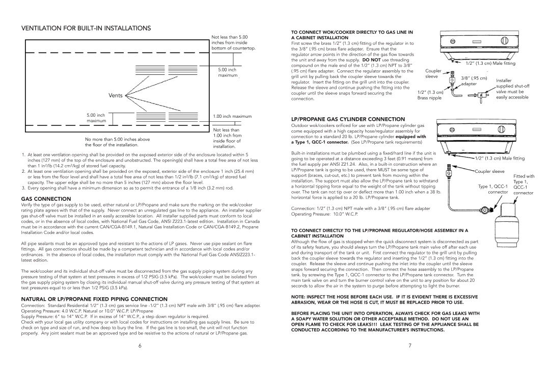
Not less than 5.00 inches from inside bottom of countertop.
5.00 inch maximum
Vents
TO CONNECT WOK/COOKER DIRECTLY TO GAS LINE IN A CABINET INSTALLATION
First screw the brass 1/2” (1.3 cm) fitting of the regulator in to the 3/8” (.95 cm) brass flare adapter. Ensure that the regulator arrow points in the direction of the gas flow towards the unit and away from the supply. DO NOT use threading compound on the male end of the 1/2” (1.3 cm) NPT to 3/8” (.95 cm) flare adapter. Connect the regulator assembly to the grill unit by pulling back the coupler sleeve towards the regulator. Insert the fitting on the grill unit into the coupler. Release the sleeve and continue pushing the fitting into the coupler until the sleeve snaps forward securing the connection.
Coupler sleeve
1/2” (1.3 cm) Brass nipple
1/2” (1.3 cm) Male fitting
3/8” (.95 cm) |
|
|
| Installer | |
adapter |
| |
| supplied | |
|
| |
| ||
|
| valve must be |
|
| easily accessible |
|
|
|
5.00inch maximum
No more than 5.00 inches above the floor of the installation.
1.00 inch maximum
Not less than
1.00inch from inside floor of installation.
LP/PROPANE GAS CYLINDER CONNECTION
Outdoor wok/cookers orificed for use with LP/Propane cylinder gas come equipped with a high capacity hose/regulator assembly for connection to a standard 20 lb. LP/Propane cylinder equipped with a Type 1,
1.At least one ventilation opening shall be provided on the exposed exterior side of the enclosure located within 5 inches (127 mm) of the top of the enclosure and unobstructed. The opening(s) shall have a total free area of not less than 1 in2/lb (14.2 cm2/kg) of stored fuel capacity.
2.At least one ventilation opening shall be provided on the exposed, exterior side of the enclosure 1 inch (25.4 mm) or less from the floor level and shall have a total free area of not less than 1/2 in2/lb (7.1 cm2/kg) of stored fuel capacity. The upper edge shall be no more than 5 inches (127 mm) above the floor level.
3.Every opening shall have a minimum dimension so as to permit the entrance of a 1/8 inch (3.2 mm) rod.
GAS CONNECTION
Verify the type of gas supply to be used, either natural or LP/Propane and make sure the marking on the wok/cooker rating plate agrees with that of the supply. Never connect an unregulated gas line to the appliance. An installer supplier gas
All pipe sealants must be an approved type and resistant to the actions of LP gases. Never use pipe sealant on flare fittings. All gas connections should be made by a competent technician and in accordance with local codes and/or ordinances. In the absence of local codes, the installation must comply with the National Fuel Gas Code ANSIZ223.1- latest edition.
The wok/cooker and its individual
NATURAL OR LP/PROPANE FIXED PIPING CONNECTION
Connection: Standard Residential 1/2” (1.3 cm) gas service line
Operating Pressure: 4.0 W.C.P. Natural or 10.0” W.C.P. LP/Propane
Supply Pressure: 6” to 14” W.C.P. If in excess of 14” W.C.P., a step down regulator is required.
Check with your local gas utility company or with local codes for instructions on installing gas supply lines. Be sure to check on type and size of run, and how deep to bury the line. If the gas line is too small, the unit will not function properly. Any joint sealant must be an approved type and be resistive to the actions of natural or LP/Propane gas.
|
|
|
|
| ||
going to be operated at a distance exceeding 3 feet (0.91 meters) from | 1/2” (1.3 cm) Male fitting |
| ||||
the fuel supply per ANSI Z21.24. Also, in a |
|
|
|
|
| |
|
|
|
|
| ||
LP/Propane tank is going to be used, there MUST be some type of |
|
|
|
|
| |
Coupler sleeve |
|
|
|
| ||
support (braces, |
|
|
|
| ||
|
|
| Fitted with | |||
|
| |||||
installation. The support must also allow the LP/Propane tank to withstand |
|
|
| Type 1, | ||
a horizontal tipping force equal to the weight of the tank without tipping |
| Type 1, |
|
| ||
over. The tank can not tip over or deflect more than 1.00 inch when a 38 lb. |
| connector |
| connector | ||
horizontal force is applied to a 20 lb. LP/Propane tank. |
|
|
|
|
|
|
|
|
|
|
|
| |
Connection: 1/2” (1.3 cm) NPT male with a 3/8” (.95 cm) flare adapter
Operating Pressure: 10.0” W.C.P.
TO CONNECT DIRECTLY TO THE LP/PROPANE REGULATOR/HOSE ASSEMBLY IN A
CABINET INSTALLATION
Although the flow of gas is stopped when the quick disconnect system is disconnected as part of its safety feature, you should always turn the LP/Propane tank main valve off after each use and during transport of the tank or unit. First connect the regulator to the grill unit by pulling back the coupler sleeve towards the regulator and inserting the 1/2” (1.3 cm) fitting into the coupler. Release the sleeve and continue pushing the inlet into the coupler until the sleeve snaps forward securing the connection. Then connect the hose assembly to the LP/Propane tank. by screwing the Type 1,
NOTE: INSPECT THE HOSE BEFORE EACH USE. IF IT IS EVIDENT THERE IS EXCESSIVE ABRASION, WEAR OR THE HOSE IS CUT, IT MUST BE REPLACED PRIOR TO USE.
BEFORE PLACING THE UNIT INTO OPERATION, ALWAYS CHECK FOR GAS LEAKS WITH A SOAPY WATER SOLUTION OR OTHER ACCEPTABLE METHOD. DO NOT USE AN OPEN FLAME TO CHECK FOR LEAKS!!! LEAK TESTING OF THE APPLIANCE SHALL BE CONDUCTED ACCORDING TO THE MANUFACTURER’S INSTRUCTIONS.
6 | 7 |