OUTDOOR—C OOKING 
30”W. Ultra
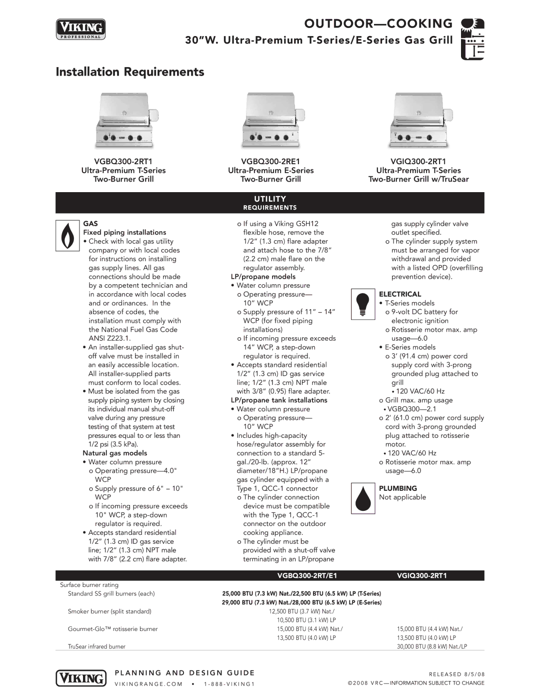
Installation Requirements
|
|
|
| UTILITY |
|
| REQUIREMENTS |
|
|
|
|
GAS
Fixed piping installations
•Check with local gas utility company or with local codes for instructions on installing gas supply lines. All gas connections should be made by a competent technician and in accordance with local codes and or ordinances. In the absence of codes, the installation must comply with the National Fuel Gas Code ANSI Z223.1.
•An
•Must be isolatedfrom the gas supply piping system by closing its individualmanual
Natural gas models
•Water column pressure
o Operating
WCP
o Supply pressure of 6" – 10"
WCP
o If incoming pressure exceeds 10" WCP,a
•Accepts standard residential 1/2” (1.3 cm) ID gas service line; 1/2” (1.3 cm) NPT male with 7/8” (2.2 cm) flare adapter.
o If using a Viking GSH12 flexible hose, remove the 1/2” (1.3 cm) flare adapter and attach hose to the 7/8” (2.2 cm) male flare on the regulator assembly.
LP/propane models
•Water column pressure o Operating pressure—
10” WCP
o Supply pressure of 11” – 14” WCP (for fixed piping installations)
o If incoming pressure exceeds 14” WCP,a
•Accepts standard residential 1/2” (1.3 cm) ID gas service line; 1/2” (1.3 cm) NPT male with 3/8” (0.95) flare adapter.
LP/propane tank installations
•Water column pressure o Operating pressure—
10” WCP
•Includes
o The cylinder connection device must be compatible with the Type 1,
o The cylinder must be provided with a
gas supply cylinder valve outlet specified.
o The cylinder supply system must be arranged for vapor withdrawal and provided with a listed OPD (overfilling prevention device).
ELECTRICAL
•
o
o Rotisserie motor max. amp
•
o 3’ (91.4 cm) power cord supply cord with
•120 VAC/60 Hz
o Grill max. amp usage
•
o 2’ (61.0 cm) power cord supply cord with
•120 VAC/60 Hz
o Rotisserie motor max. amp
PLUMBING
Not applicable
|
|
|
| ||
Surface burner rating |
|
|
|
|
|
Standard SS grill burners (each) |
|
| 25,000 BTU (7.3 kW) Nat./22,500 BTU (6.5 kW) LP | ||
|
|
| 29,000 BTU (7.3 kW) Nat./28,000 BTU (6.5 kW) LP | ||
Smoker burner (split standard) |
|
| 12,500 BTU (3.7 kW) Nat./ |
| |
|
|
| 10,500 | BTU (3.1 kW) LP |
|
|
| 15,000 | BTU (4.4 kW) Nat./ | 15,000 BTU (4.4 kW) Nat./ | |
|
|
| 13,500 | BTU (4.0 kW) LP | 13,500 BTU (4.0 kW) LP |
TruSear infrared burner |
|
|
|
| 30,000 BTU (8.8 kW) Nat./LP |
PLANNING | AND | DESIGN | GUIDE |
| RE LE A S E D 8/ 5 /0 8 |
VI KIN GRA NGE | .COM | • 1 |
| © 2 0 0 8 V R C — INFORMATION SUBJECT TO CHANGE | |