SOLA 4000 - Installation and Initial Start-Up
1 Installation
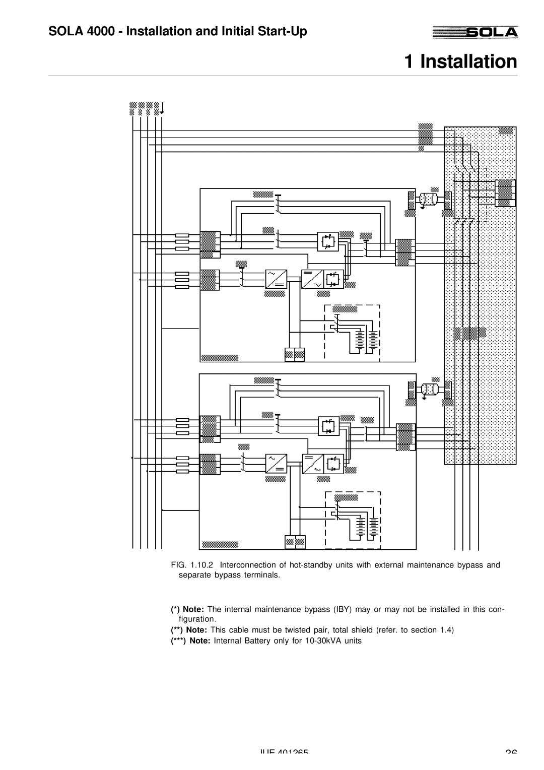
FIG. 1.10.2 Interconnection of hot-standby units with external maintenance bypass and separate bypass terminals.
(*)Note: The internal maintenance bypass (IBY) may or may not be installed in this con- figuration.
(**)Note: This cable must be twisted pair, total shield (refer. to section 1.4) (***) Note: Internal Battery only for
JUE 401265 | 36 |