SOLA 4000 - Installation and Initial Start-Up
1 Installation
1.11.1 Installation of the Interconnection Cables
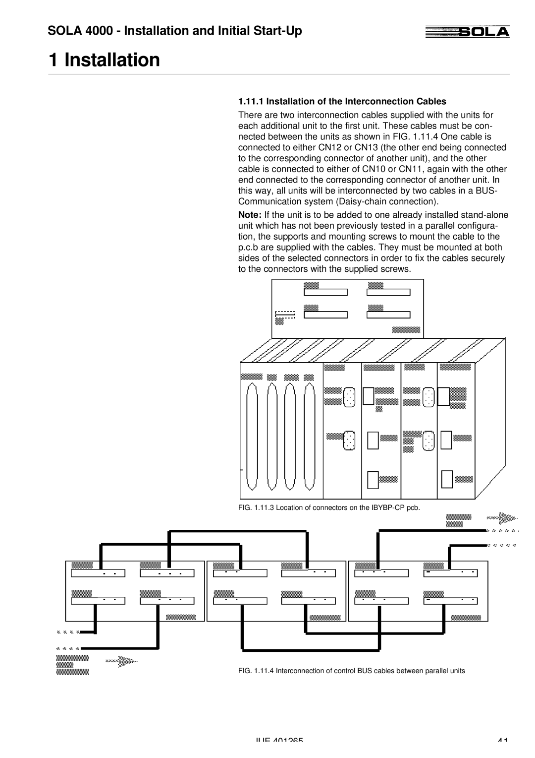
There are two interconnection cables supplied with the units for each additional unit to the first unit. These cables must be con- nected between the units as shown in FIG. 1.11.4 One cable is connected to either CN12 or CN13 (the other end being connected to the corresponding connector of another unit), and the other cable is connected to either of CN10 or CN11, again with the other end connected to the corresponding connector of another unit. In this way, all units will be interconnected by two cables in a BUS- Communication system
Note: If the unit is to be added to one already installed
FIG. 1.11.3 Location of connectors on the IBYBP-CP pcb.
FIG. 1.11.4 Interconnection of control BUS cables between parallel units
JUE 401265 | 41 |