SOLA 4000 - PCB Description
1 UPS Control Logic
PB2 Inv. ON / OFF
Inverter control and regulation (parallel configuration)
•parallel regulation of up to 8 inverters
•system control for up to 8 inverters (together with ICP pcb)
•
•load monitoring
•redundancy monitoring
LD1 PSP OK
ICP Front View
LD3 Osc. Failure
PB1 Reset
LD9 Inverter OK
LD8 Inverter volts OK
LD2 Retr. blocked
LD4 Overtemperature
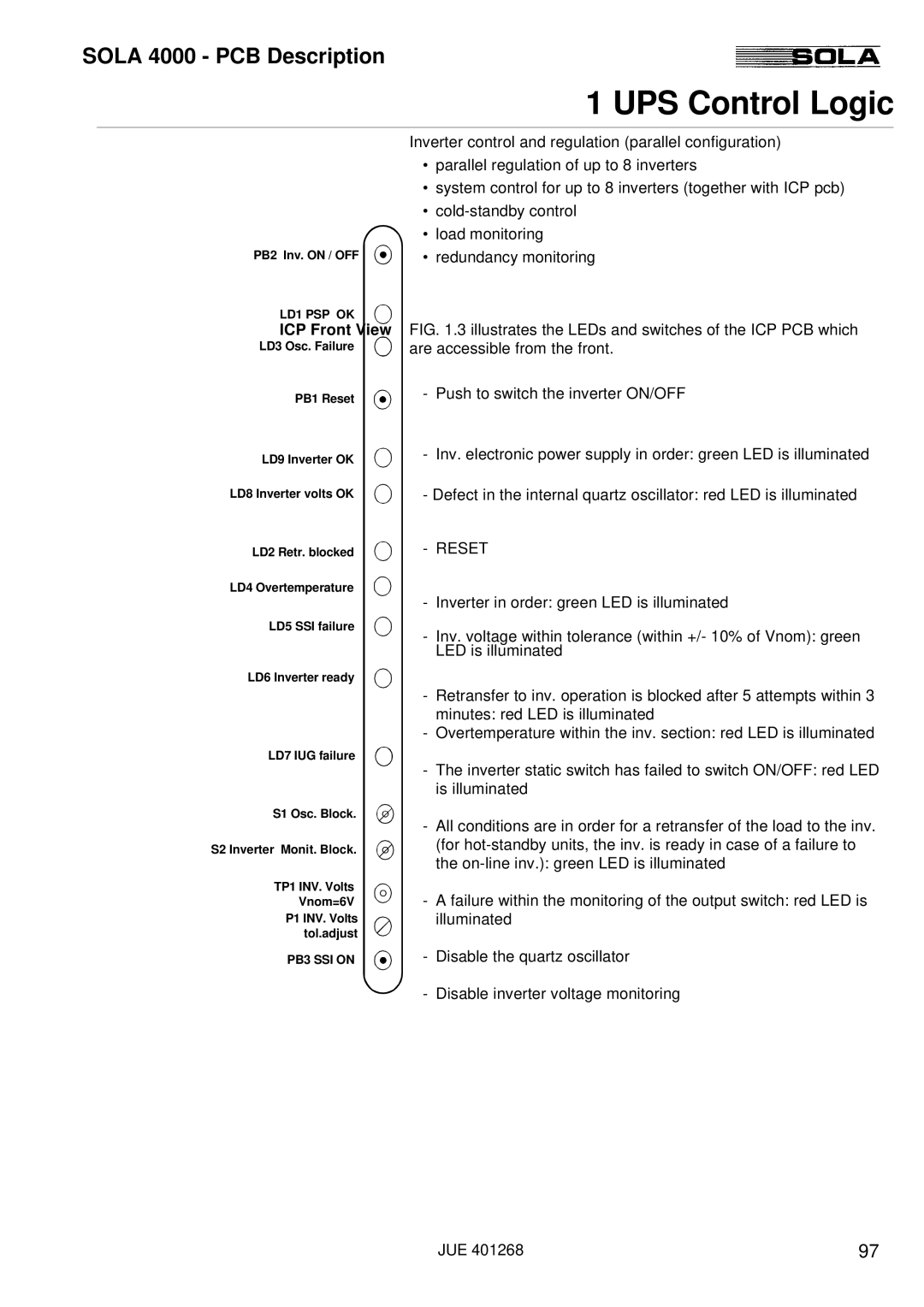
FIG. 1.3 illustrates the LEDs and switches of the ICP PCB which are accessible from the front.
-Push to switch the inverter ON/OFF
-Inv. electronic power supply in order: green LED is illuminated
-Defect in the internal quartz oscillator: red LED is illuminated
-RESET
-Inverter in order: green LED is illuminated
LD5 SSI failure
LD6 Inverter ready
-Inv. voltage within tolerance (within +/- 10% of Vnom): green LED is illuminated
LD7 IUG failure
S1 Osc. Block.
S2 Inverter Monit. Block.
TP1 INV. Volts
Vnom=6V
P1 INV. Volts
tol.adjust
PB3 SSI ON
-Retransfer to inv. operation is blocked after 5 attempts within 3 minutes: red LED is illuminated
-Overtemperature within the inv. section: red LED is illuminated
-The inverter static switch has failed to switch ON/OFF: red LED is illuminated
-All conditions are in order for a retransfer of the load to the inv. (for
-A failure within the monitoring of the output switch: red LED is illuminated
-Disable the quartz oscillator
- Disable inverter voltage monitoring
JUE 401268 | 97 |
