SOLA 4000 - Installation and Initial Start-Up
1 Installation
1.5 CPNET Interface Card
The CPNET interface card is used for remote signalling of four standard alarm conditions by means of
1.5.1 Installation
The CPNET interface card is a small pcb that is installed directly underneath the CPU/NCP pcb, inside the front door of the UPS cabinet.
It is connected to the UPS via the connector CN1 on the CPNET pcb to CN10 on the CPU/NCP pcb.
It can be connected to remote devices via two different connectors:
•CN2, a 9 pin
-IBM
-Novell
-
-Banyan Vines
•M1, a terminal block for individual configurations.
1.5.2 Functions
Contacts for the following alarm conditions are available:
Inverter Operation (N) | (CN1, pin 6) |
Bypass Operation (B) | (CN1, pin 8) |
Mains Failure (MF) | (CN1, pin 5) |
Battery Low (BL) | (CN1, pin 7) |
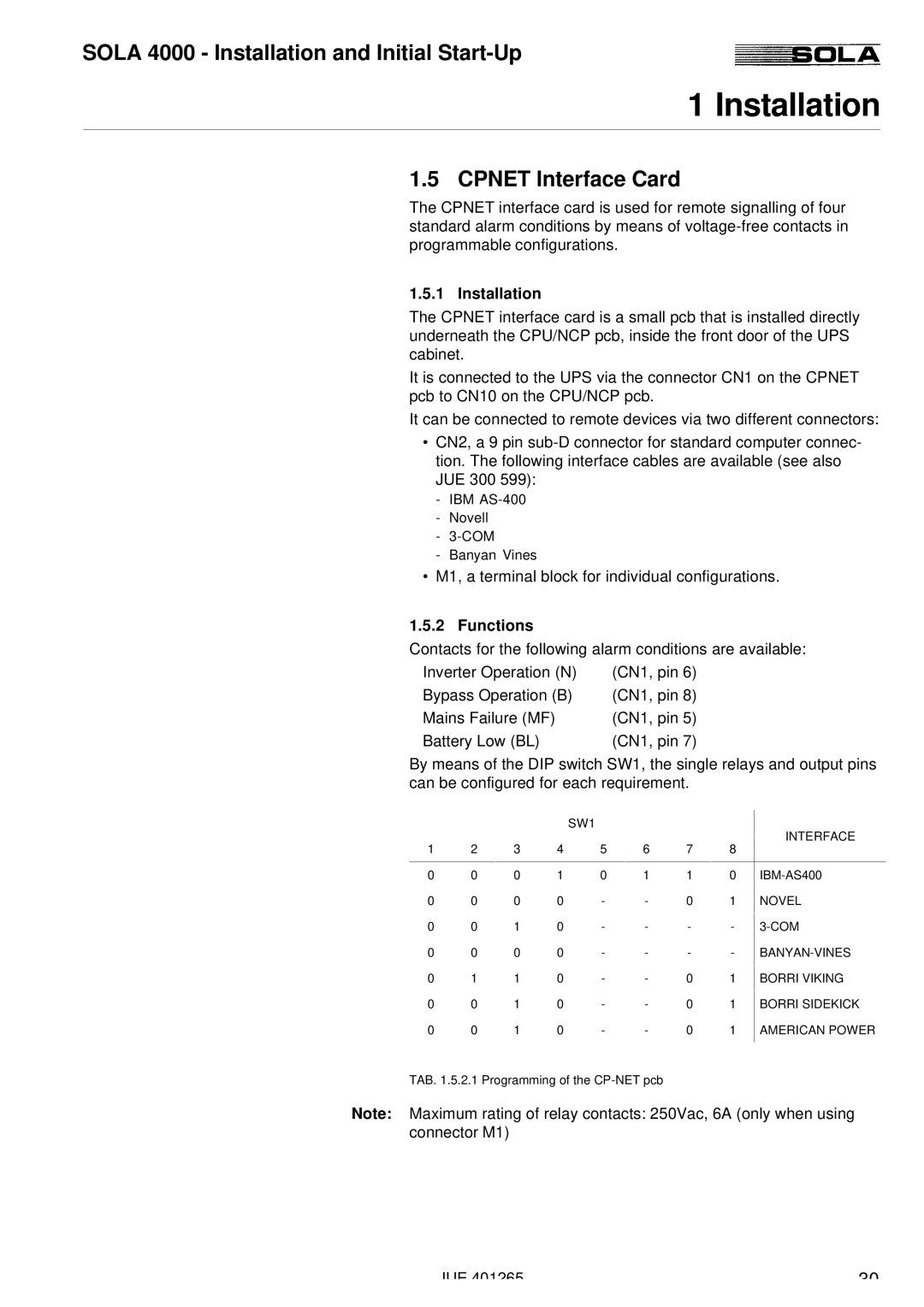
By means of the DIP switch SW1, the single relays and output pins can be configured for each requirement.
|
|
|
| SW1 |
|
|
| INTERFACE | |
1 | 2 | 3 | 4 | 5 | 6 | 7 | 8 | ||
| |||||||||
|
|
|
|
|
|
|
|
| |
0 | 0 | 0 | 1 | 0 | 1 | 1 | 0 | ||
0 | 0 | 0 | 0 | - | - | 0 | 1 | NOVEL | |
0 | 0 | 1 | 0 | - | - | - | - | ||
0 | 0 | 0 | 0 | - | - | - | - | ||
0 | 1 | 1 | 0 | - | - | 0 | 1 | BORRI VIKING | |
0 | 0 | 1 | 0 | - | - | 0 | 1 | BORRI SIDEKICK | |
0 | 0 | 1 | 0 | - | - | 0 | 1 | AMERICAN POWER | |
|
|
|
|
|
|
|
|
|
TAB. 1.5.2.1 Programming of the
Note: Maximum rating of relay contacts: 250Vac, 6A (only when using connector M1)
JUE 401265 | 30 |