Contents of JUE 401264
SOLA 4000 - General System Description
|
| Chapters |
|
|
| Figures |
|
1 | UPS ASSEMBLY | 2 |
|
|
|
| |
|
|
|
|
|
|
|
|
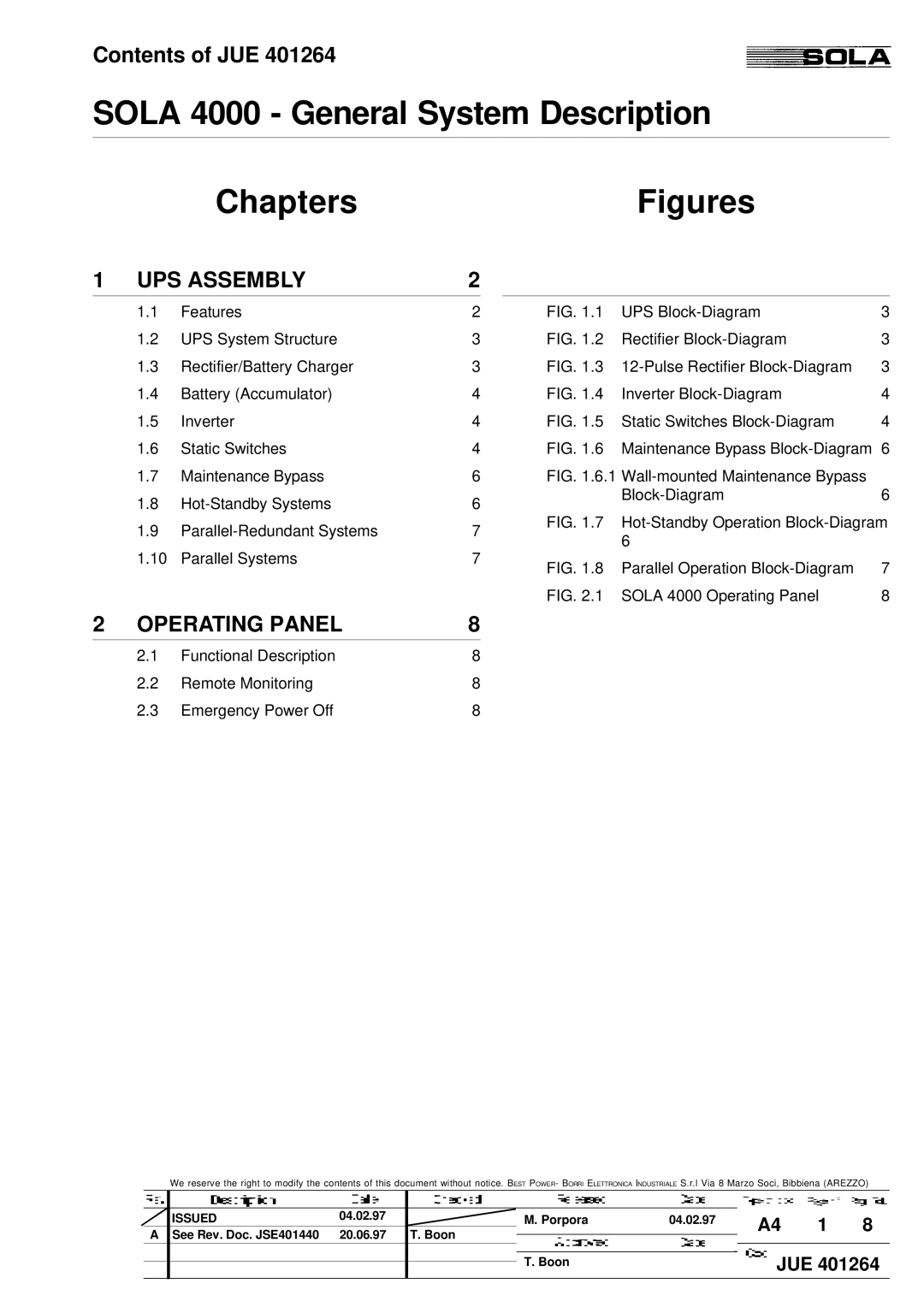
| 1.1 | Features | 2 | FIG. 1.1 | UPS | 3 | |
| 1.2 | UPS System Structure | 3 | FIG. 1.2 | Rectifier | 3 | |
| 1.3 | Rectifier/Battery Charger | 3 | FIG. 1.3 | 3 | ||
| 1.4 | Battery (Accumulator) | 4 | FIG. 1.4 | Inverter | 4 | |
| 1.5 | Inverter | 4 | FIG. 1.5 | Static Switches | 4 | |
| 1.6 | Static Switches | 4 | FIG. 1.6 | Maintenance Bypass | 6 | |
| 1.7 | Maintenance Bypass | 6 | FIG. 1.6.1 |
| ||
| 1.8 |
| 6 |
|
| 6 | |
|
|
|
| ||||
| 1.9 |
| 7 | FIG. 1.7 | |||
|
| 6 |
| ||||
| 1.10 | Parallel Systems | 7 |
|
| ||
| FIG. 1.8 Parallel Operation | 7 | |||||
|
|
|
|
| |||
|
|
|
|
| FIG. 2.1 SOLA 4000 Operating Panel | 8 | |
2 | OPERATING PANEL | 8 |
|
|
|
| |
|
|
|
|
|
|
|
|
| 2.1 | Functional Description | 8 |
|
|
| |
| 2.2 | Remote Monitoring | 8 |
|
|
| |
| 2.3 | Emergency Power Off | 8 |
|
|
| |
We reserve the right to modify the contents of this document without notice. BEST POWER- BORRI ELETTRONICA INDUSTRIALE S.r.l Via 8 Marzo Soci, Bibbiena (AREZZO)
ISSUED | 04.02.97 | M. Porpora | 04.02.97 | A4 | 1 | 8 |
A See Rev. Doc. JSE401440 | 20.06.97 | T. Boon |
| |||
|
|
|
| |||
|
| T. Boon |
| JUE 401264 | ||
