SOLA 4000 - Installation and Initial Start-Up

1 Installation

1.10.1 Installation of the Interconnection Cable

The supplied cable must be connected between the units within the system. This must be connected at either of the connectors CN12 or CN13 on the mother-board of the Inverter/Bypass electronics (IBYBP-CP) and the other end of the cable is connected to either CN12 or CN13 on the mother-board of the Inverter/Bypass elec- tronics (IBYBP-CP) of the other unit(s).

Note: If the unit is to be added to one already installed stand-alone unit which has not been previously tested in a hot-standby configu- ration, the supports and mounting screws to mount the cable to the p.c.b are supplied with the cable. They must be mounted at both sides of the selected connector in order to fix the cable securely to the connector with the supplied screws.

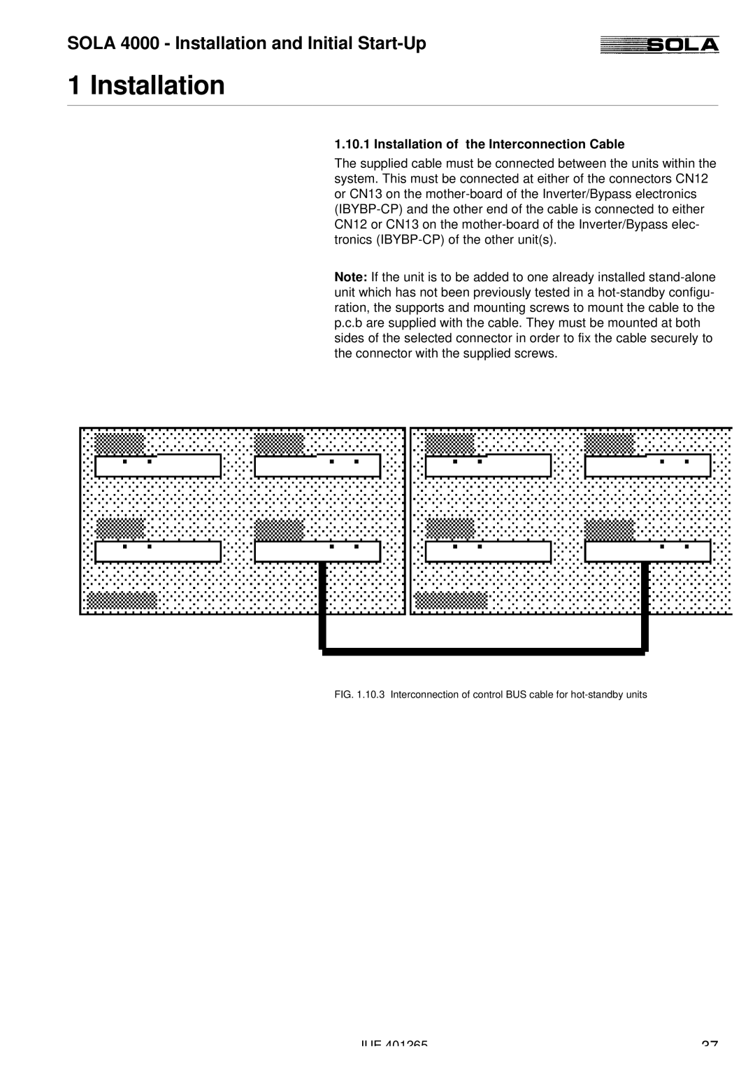
FIG. 1.10.3 Interconnection of control BUS cable for hot-standby units

JUE 401265

37

Page 37
Image 37
Powerware SOLA 4000 manual Installation of the Interconnection Cable