Contents of JUE 401265
SOLA 4000 - Installation and Initial Start-Up
ChaptersFigures
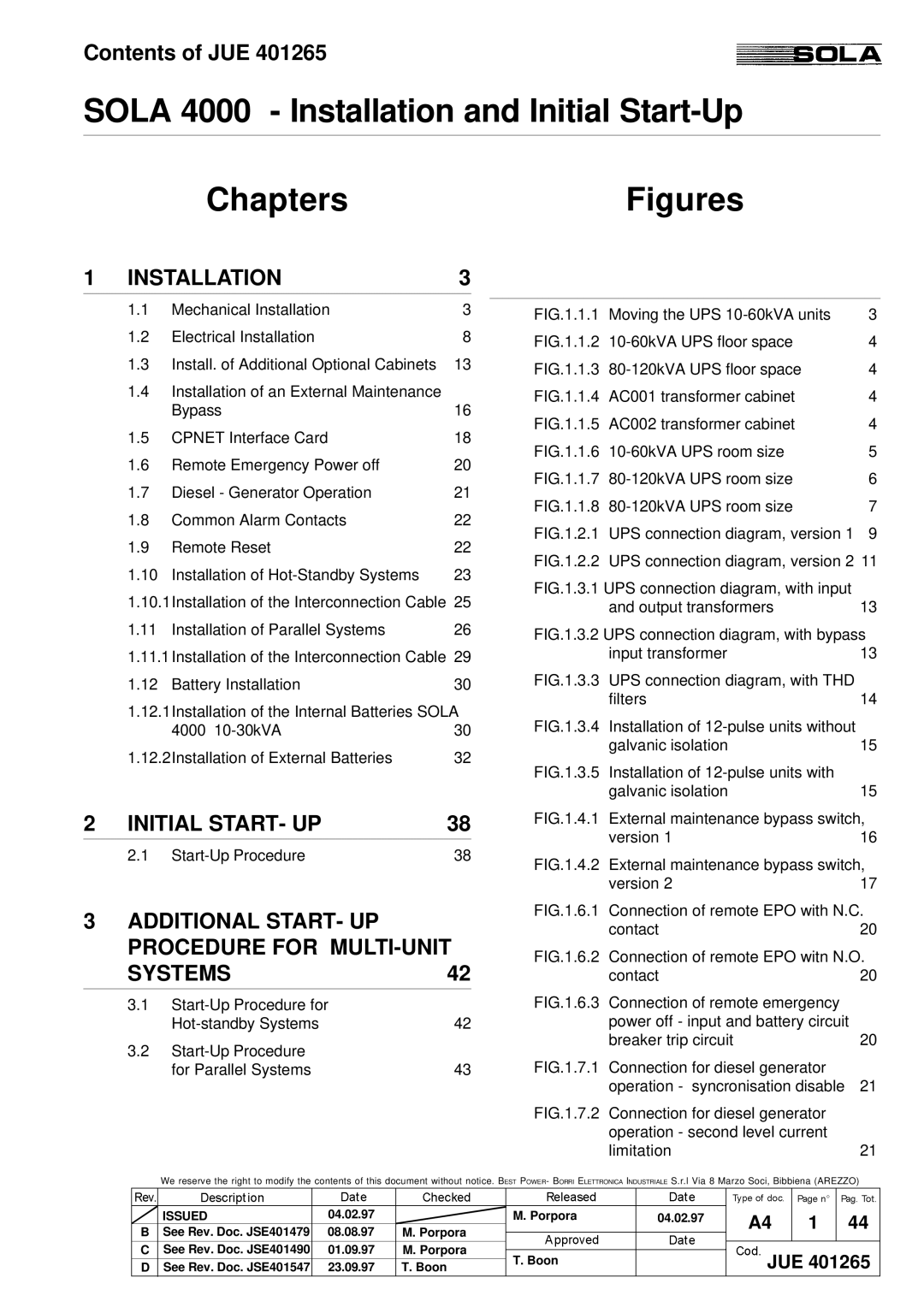
1 INSTALLATION | 3 | |
1.1 | Mechanical Installation | 3 |
1.2 | Electrical Installation | 8 |
1.3 | Install. of Additional Optional Cabinets | 13 |
1.4Installation of an External Maintenance
|
| Bypass | 16 |
| 1.5 | CPNET Interface Card | 18 |
| 1.6 | Remote Emergency Power off | 20 |
| 1.7 | Diesel - Generator Operation | 21 |
| 1.8 | Common Alarm Contacts | 22 |
| 1.9 | Remote Reset | 22 |
| 1.10 | Installation of | 23 |
| 1.10.1Installation of the Interconnection Cable | 25 | |
| 1.11 | Installation of Parallel Systems | 26 |
| 1.11.1Installation of the Interconnection Cable | 29 | |
| 1.12 | Battery Installation | 30 |
| 1.12.1Installation of the Internal Batteries SOLA | ||
|
| 4000 | 30 |
| 1.12.2Installation of External Batteries | 32 | |
2 | INITIAL START- UP | 38 | |
|
|
|
|
| 2.1 | 38 | |
3 ADDITIONAL START- UP PROCEDURE FOR MULTI-UNIT
SYSTEMS42
3.1
42 |
3.2 |
|
for Parallel Systems | 43 |
FIG.1.1.1 | Moving the UPS | 3 |
FIG.1.1.2 | 4 | |
FIG.1.1.3 | 4 | |
FIG.1.1.4 | AC001 transformer cabinet | 4 |
FIG.1.1.5 | AC002 transformer cabinet | 4 |
FIG.1.1.6 | 5 | |
FIG.1.1.7 | 6 | |
FIG.1.1.8 | 7 | |
FIG.1.2.1 | UPS connection diagram, version 1 | 9 |
FIG.1.2.2 | UPS connection diagram, version 2 11 | |
FIG.1.3.1 UPS connection diagram, with input |
| |
| and output transformers | 13 |
FIG.1.3.2 UPS connection diagram, with bypass
| input transformer | 13 |
FIG.1.3.3 | UPS connection diagram, with THD |
|
| filters | 14 |
FIG.1.3.4 | Installation of |
|
| galvanic isolation | 15 |
FIG.1.3.5 | Installation of |
|
| galvanic isolation | 15 |
FIG.1.4.1 | External maintenance bypass switch, | |
| version 1 | 16 |
FIG.1.4.2 | External maintenance bypass switch, | |
| version 2 | 17 |
FIG.1.6.1 | Connection of remote EPO with N.C. | |
| contact | 20 |
FIG.1.6.2 | Connection of remote EPO witn N.O. | |
| contact | 20 |
FIG.1.6.3 | Connection of remote emergency |
|
| power off - input and battery circuit |
|
| breaker trip circuit | 20 |
FIG.1.7.1 | Connection for diesel generator |
|
| operation - syncronisation disable | 21 |
FIG.1.7.2 | Connection for diesel generator |
|
| operation - second level current |
|
| limitation | 21 |
We reserve the right to modify the contents of this document without notice. BEST POWER- BORRI ELETTRONICA INDUSTRIALE S.r.l Via 8 Marzo Soci, Bibbiena (AREZZO)
| ISSUED | 04.02.97 |
| M. Porpora | 04.02.97 | A4 | 1 | 44 |
B | See Rev. Doc. JSE401479 | 08.08.97 | M. Porpora |
|
| |||
|
|
|
|
| ||||
C | See Rev. Doc. JSE401490 | 01.09.97 | M. Porpora | T. Boon |
| JUE 401265 | ||
D | See Rev. Doc. JSE401547 | 23.09.97 | T. Boon |
| ||||
