SOLA 4000 - Installation and Initial Start-Up
1 Installation
1.6 Remote Emergency Power off
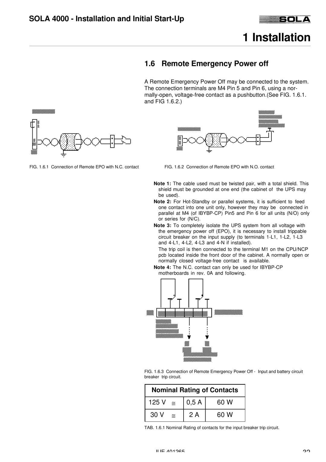
A Remote Emergency Power Off may be connected to the system. The connection terminals are M4 Pin 5 and Pin 6, using a nor-
FIG. 1.6.1 Connection of Remote EPO with N.C. contact | FIG. 1.6.2 Connection of Remote EPO with N.O. contact |
Note 1: The cable used must be twisted pair, with a total shield. This shield must be grounded at one end (the cabinet of the UPS may be used).
Note 2: For
Note 3: To completely isolate the UPS system from all voltage with the emergency power off (EPO), it is necessary to install trippable circuit breaker on the input supply (to terminals
The trip coil is then connected to the terminal M1 on the CPU/NCP pcb located inside the front door of the cabinet. A normally open or normally closed
Note 4: The N.C. contact can only be used for
FIG. 1.6.3 Connection of Remote Emergency Power Off - Input and battery circuit breaker trip circuit.
Nominal Rating of Contacts
125 V | ≅ | 0,5 A | 60 W |
|
|
|
|
30 V | ≅ | 2 A | 60 W |
|
|
|
|
TAB. 1.6.1 Nominal Rating of contacts for the input breaker trip circuit.
JUE 401265 | 32 |
