SOLA 4000 - Installation and Initial Start-Up
1 Installation
1.4Installation of an External Maintenance Bypass
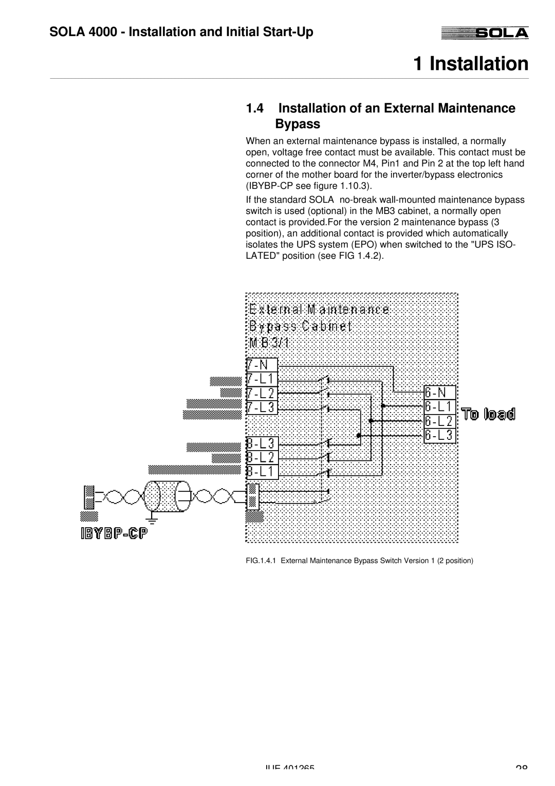
When an external maintenance bypass is installed, a normally open, voltage free contact must be available. This contact must be connected to the connector M4, Pin1 and Pin 2 at the top left hand corner of the mother board for the inverter/bypass electronics
If the standard SOLA
FIG.1.4.1 External Maintenance Bypass Switch Version 1 (2 position)
JUE 401265 | 28 |
