Viking CDMOS200, CVMOS200 service manual Description and Function of Components

Models: CVMOS200 CDMOS200 DMOS200 VMOS200

1 48
Download 48 pages 2.54 Kb
Page 13
Image 13

CDMOS200

DMOS200

VMOS200

CVMOS200

DESCRIPTION AND FUNCTION OF COMPONENTS

DOOR OPEN MECHANISM

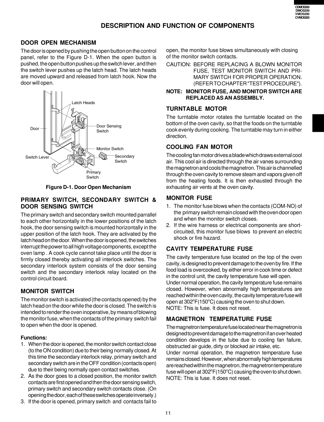
The door is opened by pushing the open button on the control panel, refer to the Figure D-1. When the open button is pushed, the open button pushes up the switch lever, and then the switch lever pushes up the latch head. The latch heads are moved upward and released from latch hook. Now the door will open.


Latch Heads

Door

Door Sensing

Switch


Monitor Switch

Switch Lever

Secondary


Switch

Primary

Switch

Figure D-1. Door Open Mechanism

open, the monitor fuse blows simultaneously with closing of the monitor switch contacts.

CAUTION: BEFORE REPLACING A BLOWN MONITOR FUSE, TEST MONITOR SWITCH AND PRI- MARY SWITCH FOR PROPER OPERATION. (REFER TO CHAPTER "TEST PROCEDURE").

NOTE: MONITOR FUSE, AND MONITOR SWITCH ARE REPLACED AS AN ASSEMBLY.

TURNTABLE MOTOR

The turntable motor rotates the turntable located on the bottom of the oven cavity, so that the foods on the turntable cook evenly during cooking. The turntable may turn in either direction.

COOLING FAN MOTOR

The cooling fan motor drives a blade which draws external cool air. This cool air is directed through the air vanes surrounding the magnetron and cools the magnetron. This air is channelled through the oven cavity to remove steam and vapors given off from the heating foods. It is then exhausted through the exhausting air vents at the oven cavity.

PRIMARY SWITCH, SECONDARY SWITCH & DOOR SENSING SWITCH

The primary switch and secondary switch mounted parrallel to each other horizontally in the lower positions of the latch hook, the door sensing switch is mounted horizontally in the upper position of the latch hook. They are activated by the latch head on the door. When the door is opened, the switches interrupt the power to all high voltage components, except the oven lamp . A cook cycle cannot take place until the door is firmly closed thereby activating all interlock switches. The secondary interlock system consists of the door sensing switch and the secondary interlock relay located on the control circuit board.

MONITOR SWITCH

The monitor switch is activated (the contacts opened) by the latch head on the door while the door is closed. The switch is intended to render the oven inoperative, by means of blowing the monitor fuse, when the contacts of the primary switch fail to open when the door is opened.

Functions:

1.When the door is opened, the monitor switch contact close (to the ON condition) due to their being normally closed. At this time the secondary interlock relay, primary switch and secondary switch are in the OFF condition (contacts open) due to their being normally open contact switches.

2.As the door goes to a closed position, the monitor switch contacts are first opened and then the door sensing switch, primary switch and secondary switch contacts close. (On openingthedoor,eachoftheseswitchesoperateinversely.)

3.If the door is opened, primary switch and contacts fail to

MONITOR FUSE

1.The monitor fuse blows when the contacts (COM-NO) of the primary switch remain closed with the oven door open and when the monitor switch closes.

2.If the wire harness or electrical components are short- circuited, this monitor fuse blows to prevent an electric shock or fire hazard.

CAVITY TEMPERATURE FUSE

The cavity temperature fuse located on the top of the oven cavity, is designed to prevent damage to the oven by fire. If the food load is overcooked, by either error in cook time or defect in the control unit, the cavity temperature fuse will open.

Under normal operation, the cavity temperature fuse remains closed. However, when abnormally high temperatures are reached within the oven cavity, the cavity temperature fuse will open at 302oF(150oC) causing the oven to shut down.

NOTE: This is fuse. It does not reset.

MAGNETRON TEMPERATURE FUSE

Themagnetrontemperaturefuselocatednearthemagnetronis designedtopreventdamagetothemagnetronifanoverheated condition develops in the tube due to cooling fan failure, obstructed air guide, dirty or blocked air intake, etc.

Under normal operation, the magnetron temperature fuse remainsclosed.However,whenabnormallyhightemperatures are reached within the magnetron, the magnetron temperature fuse will open at 302oF(150oC) causing the oven to shut down. NOTE: This is fuse. It does not reset.

11

Page 13
Image 13
Viking CDMOS200, CVMOS200 service manual Description and Function of Components

CVMOS200, CDMOS200, DMOS200, VMOS200 specifications

The Viking VMOS200, DMOS200, CDMOS200, and CVMOS200 are advanced products designed for telecommunications and power management applications. Each model showcases unique features and technologies that make them stand out in their respective fields.

The VMOS200 is built on the vertical MOSFET technology, allowing for optimized performance in high-power applications. This device excels in switching capabilities and minimizing conduction losses, leading to improved efficiency. The VMOS200 is ideal for use in power amplifiers and high-frequency applications, where reliable performance and thermal stability are crucial. Its rugged design ensures that it can withstand harsh environments, making it a preferred choice for industrial and aerospace applications.

Next, the DMOS200 employs a double-diffused MOSFET technology, which enhances its thermal performance and power handling capabilities. This model is particularly effective in low-voltage applications where efficiency is paramount. The DMOS200 features a low on-resistance characteristic, allowing for reduced energy loss during operation. Its fast switching speed enables high-frequency operation, making it suitable for RF amplifiers and motor drives.

The CDMOS200 introduces a charge-balanced design, optimizing the allocation of charge carriers within the device to minimize heat generation and improve efficiency. This model is tailored for demanding applications in communications where signal integrity and power efficiency are critical. With its high breakdown voltage and robust construction, the CDMOS200 can handle more demanding operational conditions, making it popular in cellular and satellite communication systems.

Lastly, the CVMOS200 combines the advantages of vertical and charge-balanced technologies, offering a versatile solution for a broad range of applications. This hybrid design provides high efficiency, exceptional reliability, and enhanced thermal management. The CVMOS200 is particularly well-suited for switching power supplies and audio amplification. Its compact footprint allows for integration into space-constrained designs while maintaining high performance.

In summary, the Viking series of devices—VMOS200, DMOS200, CDMOS200, and CVMOS200—offer a range of features, technologies, and characteristics tailored to meet the demands of modern power electronics and telecommunications. With their robust designs, high efficiency, and adaptability to various applications, these devices are integral components for engineers and designers looking to create cutting-edge technological solutions.