CDMOS200

DMOS200

VMOS200

CVMOS200

TEST PROCEDURES

PROCEDURE

LETTER

COMPONENT TEST

MFOIL PATTERN ON THE PRINTED WIRING BOARD TEST

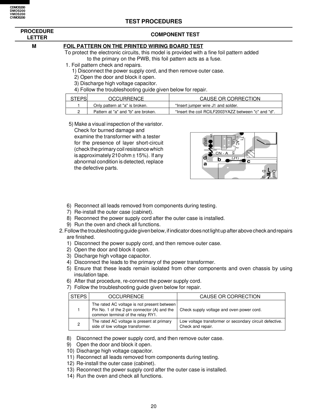
To protect the electronic circuits, this model is provided with a fine foil pattern added to the primary on the PWB, this foil pattern acts as a fuse.

1.Foil pattern check and repairs.

1)Disconnect the power supply cord, and then remove outer case.

2)Open the door and block it open.

3)Discharge high voltage capacitor.

4)Follow the troubleshooting guide given below for repair.

STEPS

OCCURRENCE

CAUSE OR CORRECTION

1

Only pattern at "a" is broken.

*Insert jumper wire J1 and solder.

2

Pattern at "a" and "b" are broken.

*Insert the coil RCILF2003YAZZ between "c" and "d".

5)Make a visual inspection of the varistor. Check for burned damage and examine the transformer with a tester for the presence of layer short-circuit (check the primary coil resistance which is approximately 210 ohm ± 15%). If any abnormal condition is detected, replace the defective parts.

VRS1

VH

1 AC

T1


2


d

CN - A

XA


b

(J1)

c


a


D U

OMIF

6)Reconnect all leads removed from components during testing.

7)Re-install the outer case (cabinet).

8)Reconnect the power supply cord after the outer case is installed.

9)Run the oven and check all functions.

2.Follow the troubleshooting guide given below, if indicator does not light up after above check and repairs are finished.

1)Disconnect the power supply cord, and then remove outer case.

2)Open the door and block it open.

3)Discharge high voltage capacitor.

4)Disconnect the leads to the primary of the power transformer.

5)Ensure that these leads remain isolated from other components and oven chassis by using insulation tape.

6)After that procedure, re-connect the power supply cord.

7)Follow the troubleshooting guide given below for repair.

STEPS

OCCURRENCE

CAUSE OR CORRECTION


The rated AC voltage is not present between


1

Pin No. 1 of the 2-pin connector (A) and the

Check supply voltage and oven power cord.


common terminal of the relay RY1.


2

The rated AC voltage is present at primary

Low voltage transformer or secondary circuit defective.

side of low voltage transformer.

Check and repair.


8)Disconnect the power supply cord, and then remove outer case.

9)Open the door and block it open.

10)Discharge high voltage capacitor.

11)Reconnect all leads removed from components during testing.

12)Re-install the outer case (cabinet).

13)Reconnect the power supply cord after the outer case is installed.

14)Run the oven and check all functions.

20

Page 22
Image 22
Viking CDMOS200, CVMOS200 service manual Steps Occurrence Cause or Correction

CVMOS200, CDMOS200, DMOS200, VMOS200 specifications

The Viking VMOS200, DMOS200, CDMOS200, and CVMOS200 are advanced products designed for telecommunications and power management applications. Each model showcases unique features and technologies that make them stand out in their respective fields.

The VMOS200 is built on the vertical MOSFET technology, allowing for optimized performance in high-power applications. This device excels in switching capabilities and minimizing conduction losses, leading to improved efficiency. The VMOS200 is ideal for use in power amplifiers and high-frequency applications, where reliable performance and thermal stability are crucial. Its rugged design ensures that it can withstand harsh environments, making it a preferred choice for industrial and aerospace applications.

Next, the DMOS200 employs a double-diffused MOSFET technology, which enhances its thermal performance and power handling capabilities. This model is particularly effective in low-voltage applications where efficiency is paramount. The DMOS200 features a low on-resistance characteristic, allowing for reduced energy loss during operation. Its fast switching speed enables high-frequency operation, making it suitable for RF amplifiers and motor drives.

The CDMOS200 introduces a charge-balanced design, optimizing the allocation of charge carriers within the device to minimize heat generation and improve efficiency. This model is tailored for demanding applications in communications where signal integrity and power efficiency are critical. With its high breakdown voltage and robust construction, the CDMOS200 can handle more demanding operational conditions, making it popular in cellular and satellite communication systems.

Lastly, the CVMOS200 combines the advantages of vertical and charge-balanced technologies, offering a versatile solution for a broad range of applications. This hybrid design provides high efficiency, exceptional reliability, and enhanced thermal management. The CVMOS200 is particularly well-suited for switching power supplies and audio amplification. Its compact footprint allows for integration into space-constrained designs while maintaining high performance.

In summary, the Viking series of devices—VMOS200, DMOS200, CDMOS200, and CVMOS200—offer a range of features, technologies, and characteristics tailored to meet the demands of modern power electronics and telecommunications. With their robust designs, high efficiency, and adaptability to various applications, these devices are integral components for engineers and designers looking to create cutting-edge technological solutions.