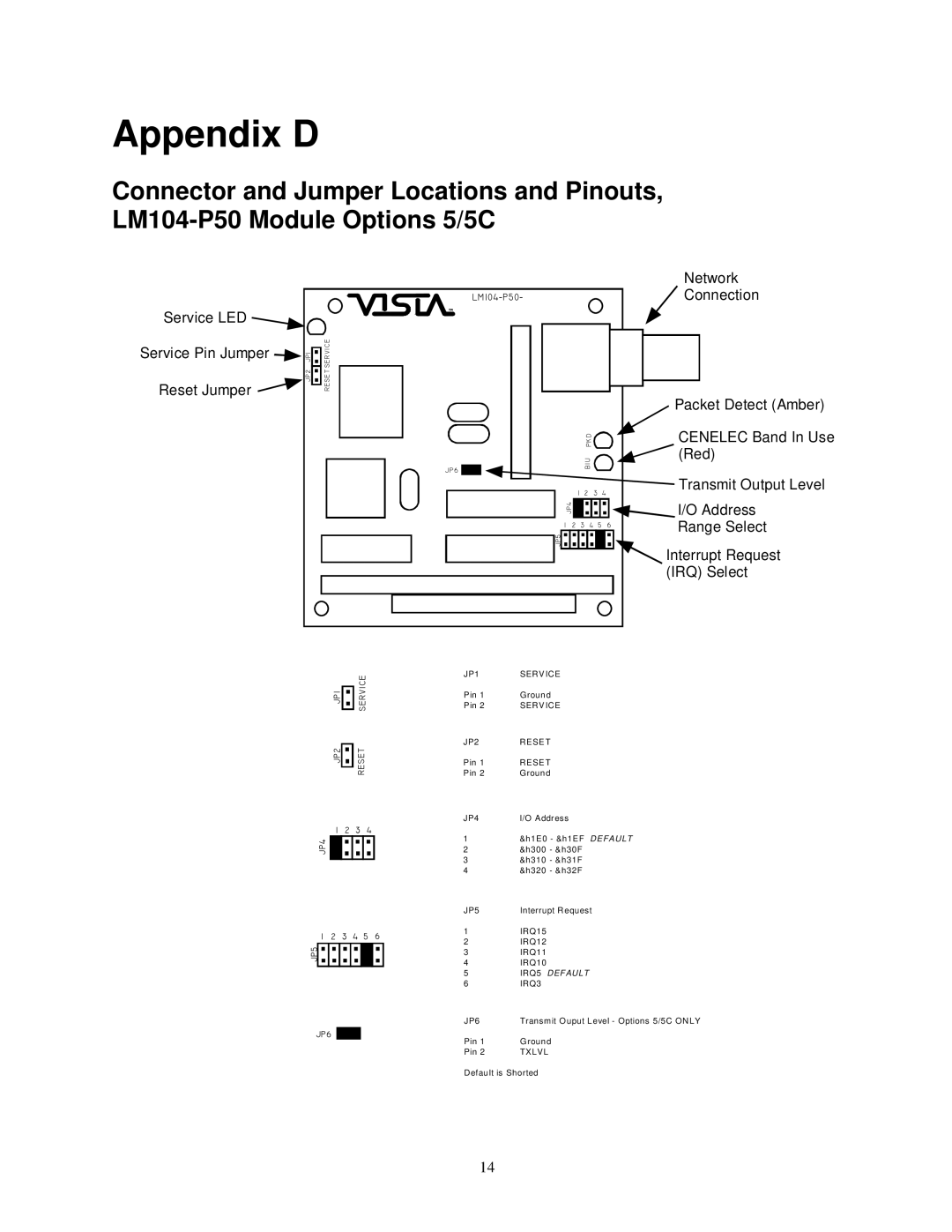
Appendix D
Connector and Jumper Locations and Pinouts,
Service LED ![]()
Service Pin Jumper | JP1 |
| SERVICE |
Reset Jumper | JP2 |
| SET |
|
| RE | |
|
|
|
Network
LM104−P50−![]() Connection
Connection
TM
|
|
|
|
|
|
|
|
|
|
|
|
|
|
|
|
|
|
|
|
|
|
|
|
|
|
|
|
|
|
|
|
|
|
|
|
|
|
|
|
|
|
|
|
|
|
|
|
|
|
|
|
|
|
|
|
|
|
|
|
|
|
|
|
|
|
|
|
|
|
|
|
|
|
|
|
|
|
|
|
|
|
|
|
|
| Packet Detect (Amber) | |
|
|
|
|
|
|
|
|
|
|
|
|
|
|
|
|
|
|
|
| ||
|
|
|
|
|
|
|
|
|
|
|
|
|
|
|
|
|
|
|
| ||
|
|
|
|
|
|
|
|
|
|
|
| PKD |
|
|
|
|
|
| CENELEC Band In Use | ||
JP6 |
|
|
|
|
|
|
|
|
|
| BIU |
|
|
|
|
|
| (Red) | |||
|
|
|
|
|
|
|
|
|
|
|
|
|
|
| |||||||
|
|
|
|
|
|
|
|
| 1 | 2 |
| 3 4 |
|
|
| Transmit Output Level | |||||
|
|
|
|
|
|
|
|
|
|
|
| ||||||||||
|
|
|
|
|
|
|
|
|
|
|
| ||||||||||
|
|
|
|
|
|
|
|
| JP4 |
|
|
|
|
|
|
|
|
|
| I/O Address | |
|
|
|
|
|
|
|
|
|
|
|
|
|
|
|
|
|
|
| |||
1 | 2 | 3 | 4 | 5 |
| 6 |
| Range Select | |||||||||||||
|
|
|
|
|
|
|
|
|
|
|
|
|
|
|
|
|
|
|
|
| |
|
|
|
|
|
|
| JP5 |
|
|
|
|
|
|
|
|
|
|
|
| Interrupt Request | |
|
|
|
|
|
|
|
|
|
|
|
|
|
|
|
|
|
|
| |||
|
|
|
|
|
|
|
|
|
|
|
|
|
|
|
|
|
|
|
| ||
(IRQ) Select
|
| JP1 |
| SERVICE |
| ||
|
| JP2 |
| RESET |
| ||
| 1 | 2 | 3 | 4 |
|
| |
JP4 |
|
|
|
|
|
|
|
|
|
|
|
|
|
| |
1 | 2 | 3 | 4 | 5 |
| 6 | |
JP5 |
|
|
|
|
|
|
|
|
|
|
|
|
|
| |
|
|
|
|
|
|
|
|
JP6 ![]()
JP1 | SERV ICE |
Pin 1 | Ground |
Pin 2 | SERVICE |
JP2 | RESET |
Pin 1 | RESET |
Pin 2 | Ground |
JP4 | I/O Address |
1&h1E0 - &h1EF DEFAULT
2&h300 - &h30F
3&h310 - &h31F
4&h320 - &h32F
JP5 | Interrupt Request |
1IRQ15
2IRQ12
3IRQ11
4IRQ10
5IRQ5 DEFAULT
6IRQ3
JP6 | Transmit Ouput Level - Options 5/5C ONLY |
Pin 1 | Ground |
Pin 2 | TXLVL |
Default is Shorted
14
