
FD8365EHV specifications
The Vivotek FD8365EHV is a state-of-the-art outdoor surveillance camera designed for a variety of security applications. With its advanced features and technologies, this camera stands out in the vast market of surveillance equipment, making it an ideal choice for businesses and residential properties alike.One of the main features of the FD8365EHV is its high-definition 2MP image sensor that delivers crystal-clear video resolution of 1920x1080 pixels. This level of clarity is essential for identifying faces, license plates, and other critical details during monitoring. Additionally, the camera offers a frame rate of up to 30 frames per second, ensuring that even fast-moving objects are captured smoothly.
The FD8365EHV is equipped with a robust IR-cut filter and infrared (IR) illumination, enabling optimal performance in low-light conditions. With a nighttime range of up to 30 meters, this camera can provide reliable surveillance around the clock, maintaining its effectiveness even on the darkest nights. It also features WDR Pro technology, which enhances video quality in challenging lighting environments, ensuring that both bright and dark areas are well represented.
Another significant aspect of the FD8365EHV is its durable housing. Rated IP66 for dust and water resistance, this camera is built to withstand harsh weather conditions, making it suitable for outdoor installations. Additionally, it is constructed using weatherproof materials, which further contributes to its resilience and longevity.
Vivotek has incorporated H.265 video compression technology into the FD8365EHV, which allows for reduced bandwidth and storage requirements without sacrificing video quality. This efficiency is particularly beneficial for businesses looking to optimize their surveillance systems while maintaining high standards of video quality.
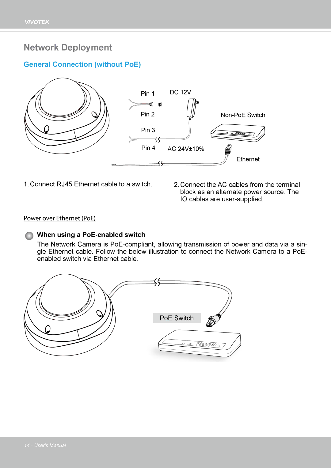
Furthermore, the FD8365EHV supports Power over Ethernet (PoE), simplifying the installation process and reducing the need for multiple cables. This feature enables the camera to be powered directly through the Ethernet cable, thereby eliminating the need for additional power sources.
In terms of integration, the Vivotek FD8365EHV is compatible with various video management systems and third-party applications, allowing for effortless incorporation into existing security setups. Its ONVIF compliance guarantees interoperability with a wide range of devices.
In conclusion, the Vivotek FD8365EHV is a versatile and high-performance surveillance camera that combines advanced imaging technologies, robust durability, and efficient data management. Its comprehensive features make it an excellent choice for any security-conscious environment.