Installation
In this manual, "User" refers to whoever has access to the Network Camera, and "Administrator" refers to the person who can configure the Network Camera and grant user access to the camera.
Hardware installation
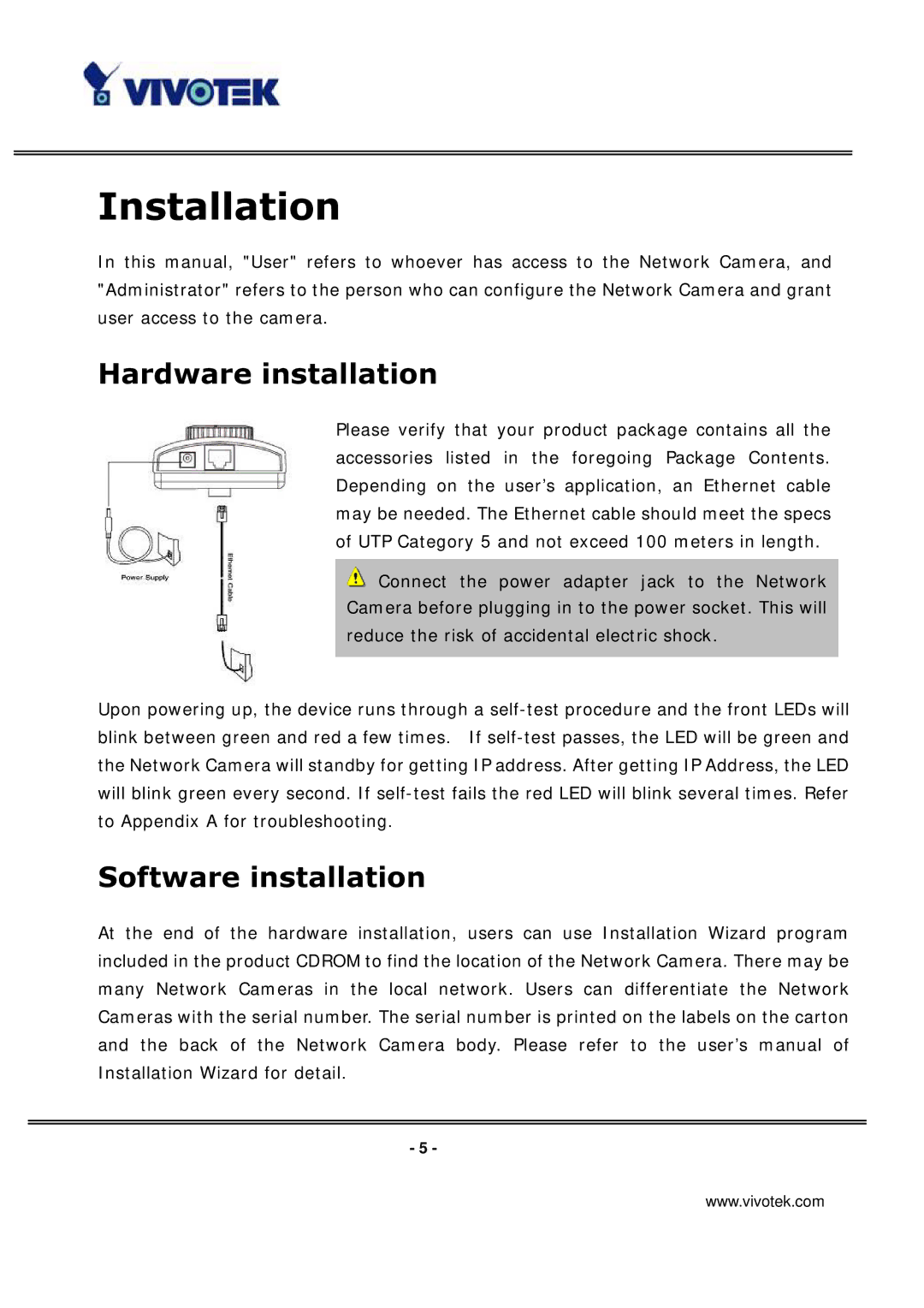
Please verify that your product package contains all the accessories listed in the foregoing Package Contents. Depending on the user’s application, an Ethernet cable may be needed. The Ethernet cable should meet the specs of UTP Category 5 and not exceed 100 meters in length.
![]() Connect the power adapter jack to the Network Camera before plugging in to the power socket. This will reduce the risk of accidental electric shock.
Connect the power adapter jack to the Network Camera before plugging in to the power socket. This will reduce the risk of accidental electric shock.
Upon powering up, the device runs through a
Software installation
At the end of the hardware installation, users can use Installation Wizard program included in the product CDROM to find the location of the Network Camera. There may be many Network Cameras in the local network. Users can differentiate the Network Cameras with the serial number. The serial number is printed on the labels on the carton and the back of the Network Camera body. Please refer to the user’s manual of Installation Wizard for detail.
- 5 -
www.vivotek.com