Installation
In this manual, "User" refers to whoever has access to the Network Camera, and "Administrator" refers to the person who can configure the Network Camera and grant user access to the camera.
Hardware installation
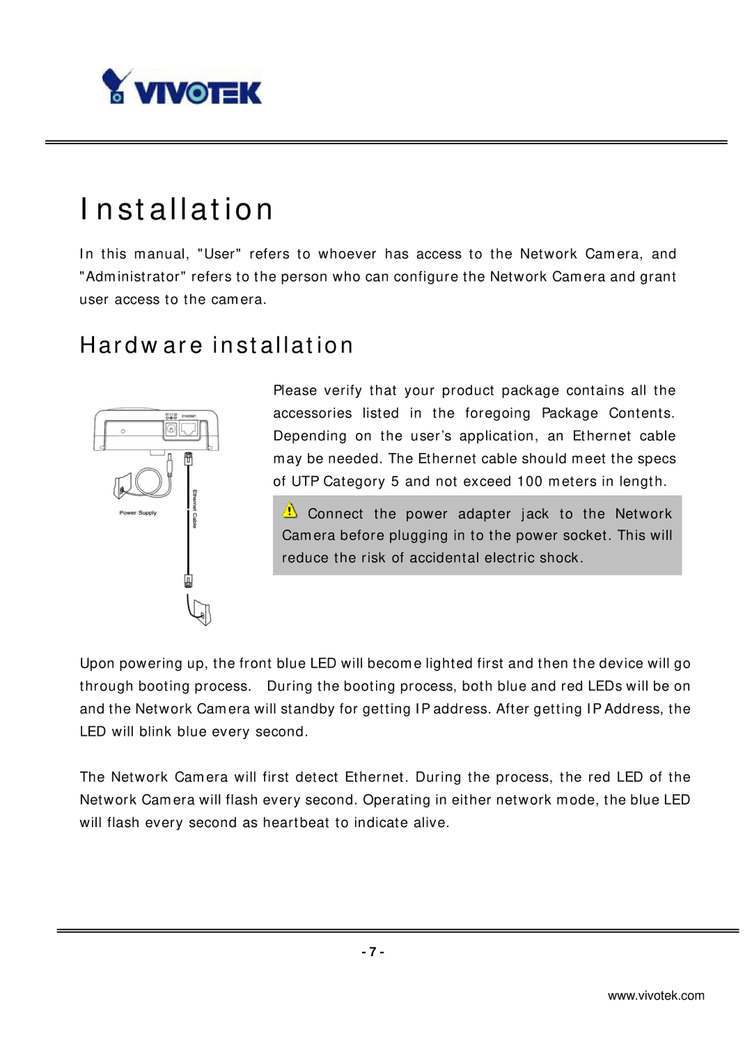
Please verify that your product package contains all the accessories listed in the foregoing Package Contents. Depending on the user’s application, an Ethernet cable may be needed. The Ethernet cable should meet the specs of UTP Category 5 and not exceed 100 meters in length.
![]() Connect the power adapter jack to the Network Camera before plugging in to the power socket. This will reduce the risk of accidental electric shock.
Connect the power adapter jack to the Network Camera before plugging in to the power socket. This will reduce the risk of accidental electric shock.
Upon powering up, the front blue LED will become lighted first and then the device will go through booting process. During the booting process, both blue and red LEDs will be on and the Network Camera will standby for getting IP address. After getting IP Address, the LED will blink blue every second.
The Network Camera will first detect Ethernet. During the process, the red LED of the Network Camera will flash every second. Operating in either network mode, the blue LED will flash every second as heartbeat to indicate alive.
- 7 -
www.vivotek.com