VIVOTEK - A Leading Provider of Multimedia Communication Solutions
Physical description
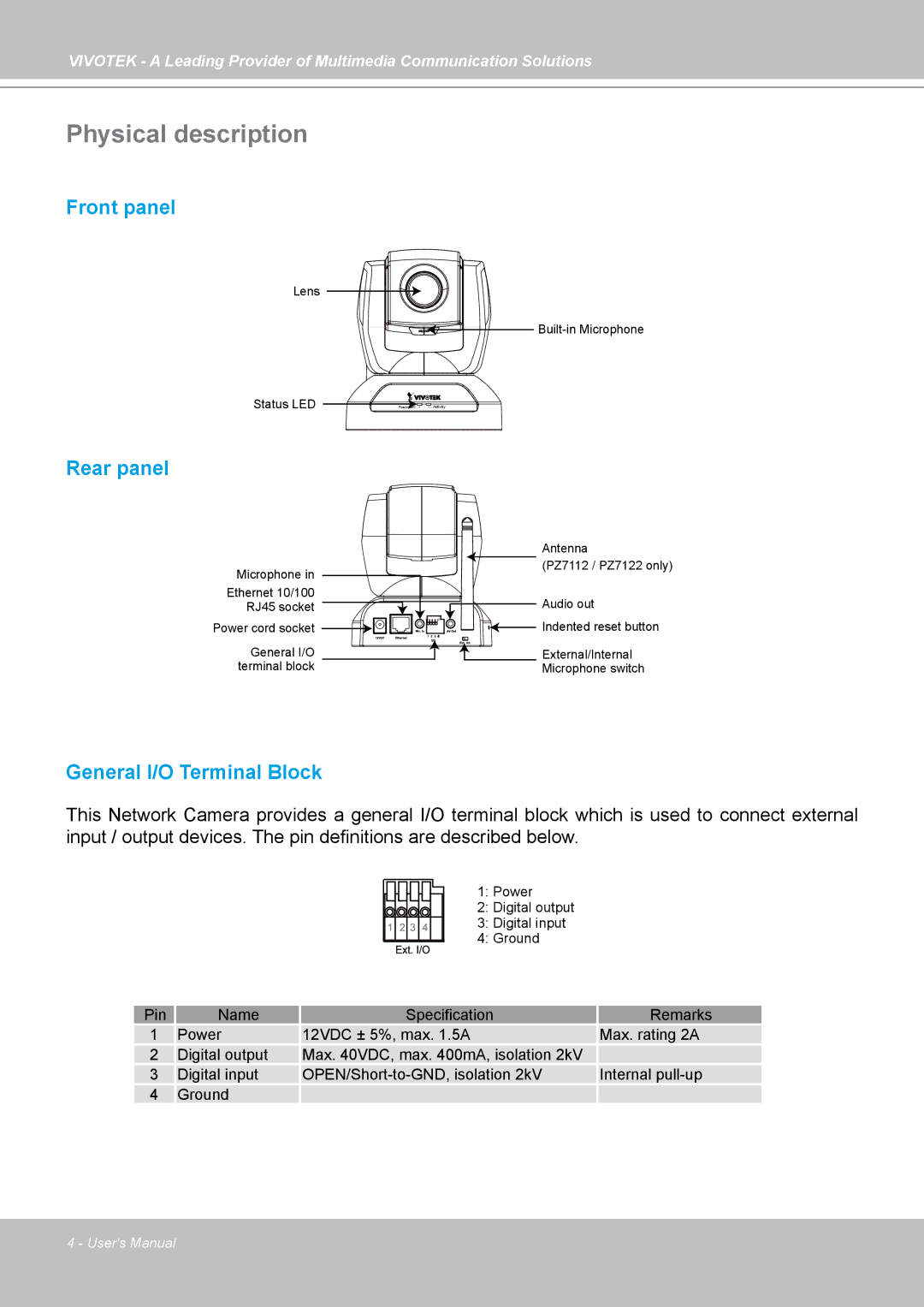
Front panel
Lens
Status LED | Power/MICActivity |
Rear panel
Microphone in
Ethernet 10/100
RJ45 socket
Power cord socket
General I/O terminal block
Antenna
(PZ7112 / PZ7122 only)
Audio out
AV | Indented reset button |
e e |
|
| External/Internal |
| Microphone switch |
General I/O Terminal Block
This Network Camera provides a general I/O terminal block which is used to connect external input / output devices. The pin definitions are described below.
1: Power
2: Digital output
3: Digital input
4: Ground
Pin | Name | Specification | Remarks |
1 | Power | 12VDC ± 5%, max. 1.5A | Max. rating 2A |
2 | Digital output | Max. 40VDC, max. 400mA, isolation 2kV |
|
3 | Digital input | Internal | |
4 | Ground |
|
|
4 - User's Manual