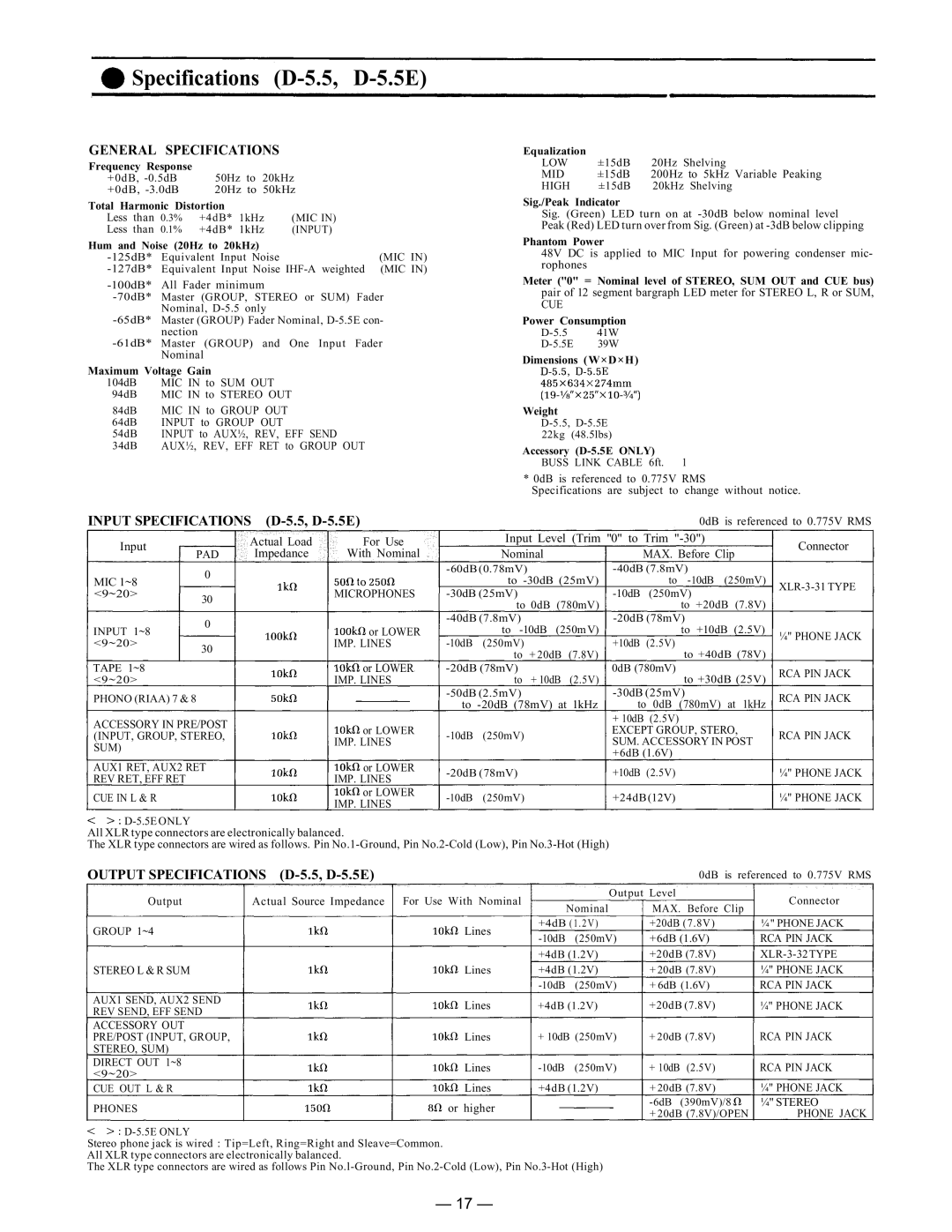
Specifications (D-5.5, D-5.5E)
GENERAL SPECIFICATIONS
Frequency Response |
|
| |
+0dB, | 50Hz to 20kHz | ||
+0dB, | 20Hz to 50kHz | ||
Total Harmonic Distortion |
| ||
Less than | 0.3% | +4dB* 1kHz | (MIC IN) |
Less than | 0.1% | +4dB* 1kHz | (INPUT) |
Hum and Noise (20Hz to 20kHz) |
| ||
Equivalent Input Noise | (MIC IN) | ||
Equivalent Input Noise | |||
All Fader minimum |
| ||
Master (GROUP, STEREO or SUM) Fader | |||
Nominal, |
| ||
Master (GROUP) Fader Nominal, | |||
| nection |
|
|
(GROUP) and One Input Fader | |||
| Nominal |
| |
Maximum Voltage Gain
104dB MIC IN to SUM OUT
94dB MIC IN to STEREO OUT
84dB MIC IN to GROUP OUT
64dB INPUT to GROUP OUT
54dB INPUT to AUX½, REV, EFF SEND
34dB AUX½, REV, EFF RET to GROUP OUT
INPUT SPECIFICATIONS |
| |
Input | Actual Load | For Use |
Equalization |
|
|
LOW | ±15dB | 20Hz Shelving |
MID | ±15dB | 200Hz to 5kHz Variable Peaking |
HIGH | ±15dB | 20kHz Shelving |
Sig./Peak Indicator
Sig. (Green) LED turn on at
Peak (Red) LED turn over from Sig. (Green) at
Phantom Power
48V DC is applied to MIC Input for powering condenser mic- rophones
Meter ("0" = Nominal level of STEREO, SUM OUT and CUE bus)
pair of 12 segment bargraph LED meter for STEREO L, R or SUM,
CUE
Power Consumption
Dimensions (W×D×H)
Weight
Accessory (D-5.5E ONLY)
BUSS LINK CABLE 6ft. 1
* 0dB is referenced to 0.775V RMS
Specifications are subject to change without notice.
0dB is referenced to 0.775V RMS
Input Level (Trim "0" to Trim
Connector
| PAD | Impedance | With Nominal |
MIC 1~8 | 0 |
|
|
|
| MICROPHONES | |
<9~20> | 30 |
| |
|
|
| |
INPUT 1~8 | 0 |
| or LOWER |
|
| ||
<9~20> | 30 |
| IMP. LINES |
|
|
| |
TAPE 1~8 |
|
| or LOWER |
<9~20> |
|
| IMP. LINES |
PHONO (RIAA) 7 & 8 |
|
| |
ACCESSORY IN PRE/POST |
| or LOWER | |
(INPUT, GROUP, STEREO, |
| ||
| IMP. LINES | ||
SUM) |
|
| |
|
|
| |
AUX1 RET, AUX2 RET |
| or LOWER | |
Nominal
to
to 0dB (780mV)
to
to + 20dB (7.8V)
to + 10dB (2.5V)
to
MAX. Before Clip
to
to +20dB (7.8V)
to +10dB (2.5V)
+10dB (2.5V)
to +40dB (78V)
0dB (780mV)
to +30dB (25V)
to 0dB (780mV) at 1kHz
+ 10dB (2.5V)
EXCEPT GROUP, STERO,
SUM. ACCESSORY IN POST +6dB (1.6V)
¼" PHONE JACK
RCA PIN JACK RCA PIN JACK
RCA PIN JACK
REV RET, EFF RET | IMP. LINES | |
CUE IN L & R | or LOWER | |
IMP. LINES | ||
|
D-5.5E ONLY
+10dB (2.5V) | ¼" PHONE JACK | |
+24dB(12V) | ¼" PHONE JACK |
All XLR type connectors are electronically balanced.
The XLR type connectors are wired as follows. Pin
OUTPUT SPECIFICATIONS |
|
| 0dB is referenced to 0.775V RMS | |||
Output | Actual Source Impedance | For Use With Nominal | Output Level | Connector | ||
Nominal | MAX. Before Clip | |||||
|
|
|
| |||
GROUP 1~4 |
| Lines | +4dB (1.2V) | +20dB (7.8V) | ¼" PHONE JACK | |
| +6dB (1.6V) | RCA PIN JACK | ||||
|
|
| ||||
|
|
| +4dB (1.2V) | +20dB (7.8V) | ||
STEREO L & R SUM |
| Lines | +4dB (1.2V) | + 20dB (7.8V) | ¼" PHONE JACK | |
|
|
| + 6dB (1.6V) | RCA PIN JACK | ||
AUX1 SEND, AUX2 SEND |
| Lines | +4dB (1.2V) | +20dB (7.8V) | ¼" PHONE JACK | |
REV SEND, EFF SEND |
| |||||
|
|
|
|
| ||
ACCESSORY OUT |
|
|
|
| RCA PIN JACK | |
PRE/POST (INPUT, GROUP, |
| Lines | + 10dB (250mV) | + 20dB (7.8V) | ||
STEREO, SUM) |
|
|
|
|
| |
DIRECT OUT 1~8 |
| Lines | + 10dB (2.5V) | RCA PIN JACK | ||
<9~20> |
| |||||
|
|
|
|
| ||
CUE OUT L & R |
| Lines | +4dB (1.2V) | + 20dB (7.8V) | ¼" PHONE JACK | |
PHONES |
| or higher |
| ¼" STEREO | ||
|
| + 20dB (7.8V)/OPEN | PHONE JACK | |||
|
|
|
| |||
Stereo phone jack is wired : Tip=Left, Ring=Right and Sleave=Common.
All XLR type connectors are electronically balanced.
The XLR type connectors are wired as follows Pin
— 17 —
