Manuals
/
Vizio
/
TV and Video
/
Flat Panel Television
Vizio
GV42L HDTV, L42HDTV10A Random Read Accesses CAS Latencies Burst Length = 2, 4 or
Models:
GV42L HDTV
L42HDTV10A
1
72
107
107
Download
107 pages
57.67 Kb
69
70
71
72
73
74
75
76
Troubleshooting
Specification
Block Diagram
RGB Signal
Factory preset timings
Command Truth Table
Type TV RF connector
Weight
Operating Precautions
Output power measurement
Page 72
Image 72
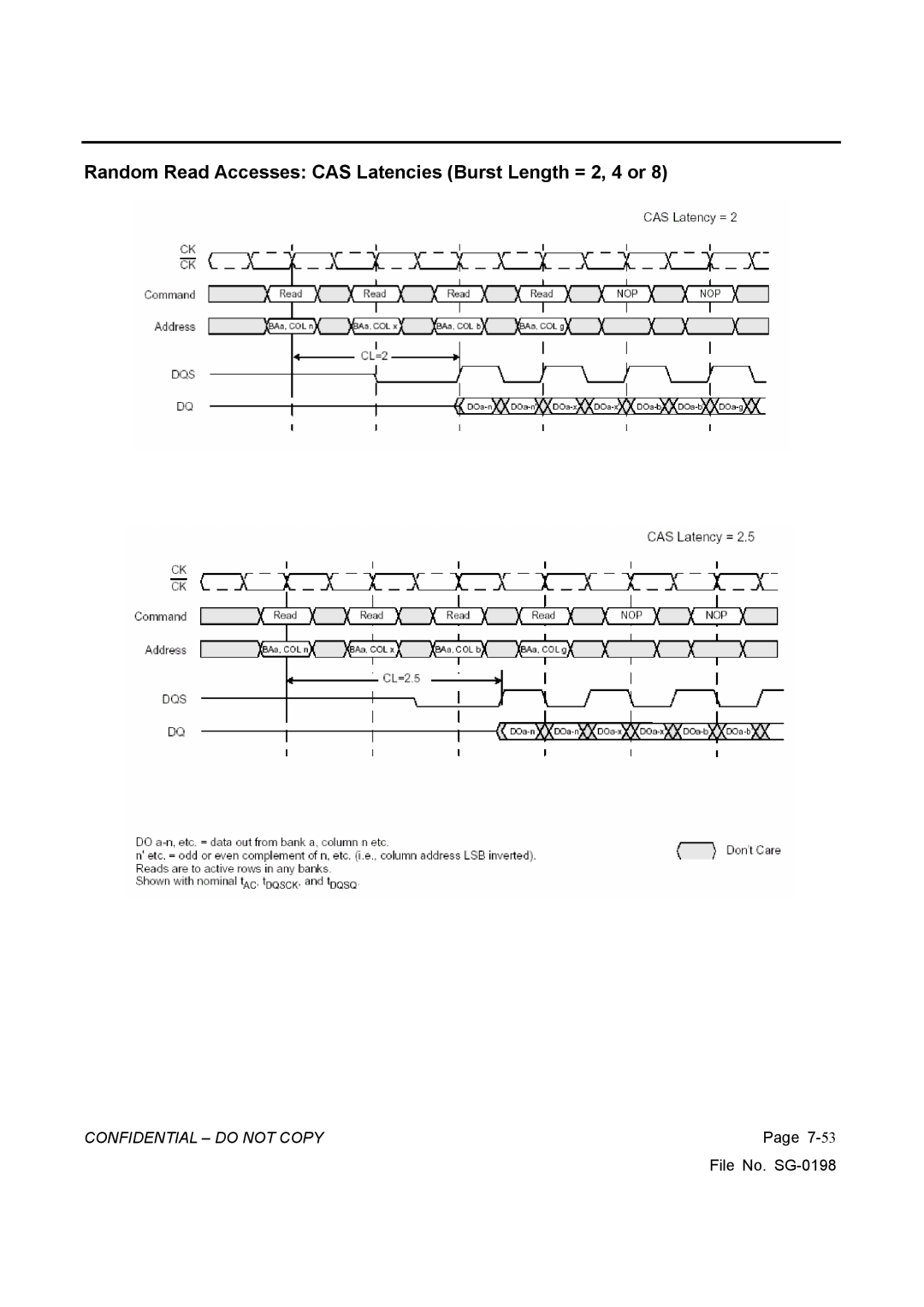
Random Read Accesses: CAS Latencies (Burst Length = 2, 4 or 8)
CONFIDENTIAL – DO NOT COPY
Page
7-
53
File No.
SG-0198
Page 71
Page 73
Page 72
Image 72
Page 71
Page 73
Contents
Vizio GV42L Hdtv
Table of Contents
Vinc
Features
Specification
Optical Characteristics
Power Supply
Dimensions Physical dimension Width 1066 mm
Weight Physical weight
Mounting Precautions
Speaker
Operating Precautions
Handling Precautions for Protection
On Screen Display
TV Source
RGB Mode
AV Component Mode
Hdmi MODE:
Confidential do not Copy
Factory preset timings
Pin Assignment
Hdmi Connect PIN Assignment
Type TV RF connector
RGB Signal
Main Board I/o Connections
Theory of Circuit Operation
MT8202 Application
YPbPr/Scart/D-connector
Video input
Decoder
Digital port
Support Formats
Supporting OSD mirror and upside down
2D-Graphic/OSD processor
I/O ports are configured as follows:
Microprocessor interface
Video processor 1.Color Management
Dram Usage
DDR Sdram V58C2128164SBI5 Application
Pin description
Command Truth Table
Power-UpFunctional Description
Mode Register Set MRS
Precharge
Bank Activate Command
Read Operation
Precharge Timing During Read Operation
Burst Stop Command
Precharge Timing During Write Operation
Burst Write Operation
MX29LV160BTTC Flash Application
Block Diagram Command Definitions
Write COMMANDS/COMMAND Sequences
READ/RESET Command
Reading Array Data
WM8776 Application
Audio sample rate
Slave mode
Confidential do not Copy
MT8293 Application
Tmds Digital Core
Active port detection
Hdcp Decryption
Video Data Conversion and Video Output
I2c Interface to Display Controller
TDA8946 Application
Block diagram Input configuration
Output power measurement
Mode selection
MT5351 Application
General Feature List
CGMS/WSS
Confidential do not Copy
MX29LV320BTTC Flash Application
Confidential do not Copy
Block Diagram
BUS OPERATION--1
Write COMMANDS/COMMAND Sequences
BUS OPERATION--2
Table A. MX29LV320AT/B Command Definitions
Standby Mode
Reset Operation
Software Command Definitions
Write Protect WP
Write Operation Status
Table B. Write Operation Status
Fig C. Command Write Operation Fig D. Read Timing Waveforms
Fig E. Reset Timing Waveform
Block Diagram 16Mb x
DDR Sdram NT5DS16M16CS-5T Application
Functional Description
Pin Configuration 400mil Tsop II x4 / x8
Mode Register Operation Operating Mode
Extended Mode Register
Extended Mode Register Definition
Truth Table a Commands
Active
Read
Write
Auto Refresh
Self Refresh
Operations
Reads
Random Read Accesses CAS Latencies Burst Length = 2, 4 or
Read Command
Write Command
Data Input Write Data Output Read
Waveforms
PC MODE1366X768 60HZ
CH1 Green # FB27 CH2 Vgavsync L22
CH1 Vgal R193 CH2 Avol R194 CH1 PCL CE70+ PCL CE70
AV&TV Mode AV1/AV2/TV Video
Confidential do not Copy
CH1 Dacbclk U23 PIN4 CH1 Dacmclk U23 PIN5
Component Mode Component 1/2
CH1YCBCRL2L19 CH2 2A33 U22 PIN11 CH1 AVL CE71+CH2 Auspl R304
Hdmi 1&2
Confidential do not Copy
DTV HD
Confidential do not Copy
CH1 Vovsync DU9 PIN W1 CH1 Vode DU9 PIN W2
CH1 Vopclk DU9 PIN
Trouble shooting
Monitor Display Nothing PC Mode
TV, Composite VIDEO1, 2, S-VIDEO is not Display Correctly
COMPONENT1, 2 is not Display Correctly
Hdmi is not Display Correctly
Trouble of DC-DC Converter
Trouble of DDC Reading
Block Diagram
System Block Diagram Wxga panel
Confidential do not Copy
Main Board Block Diagram
Page
Page
Page
Page
Page
Page
Page
Top
Page
Image
Contents