Input Connector
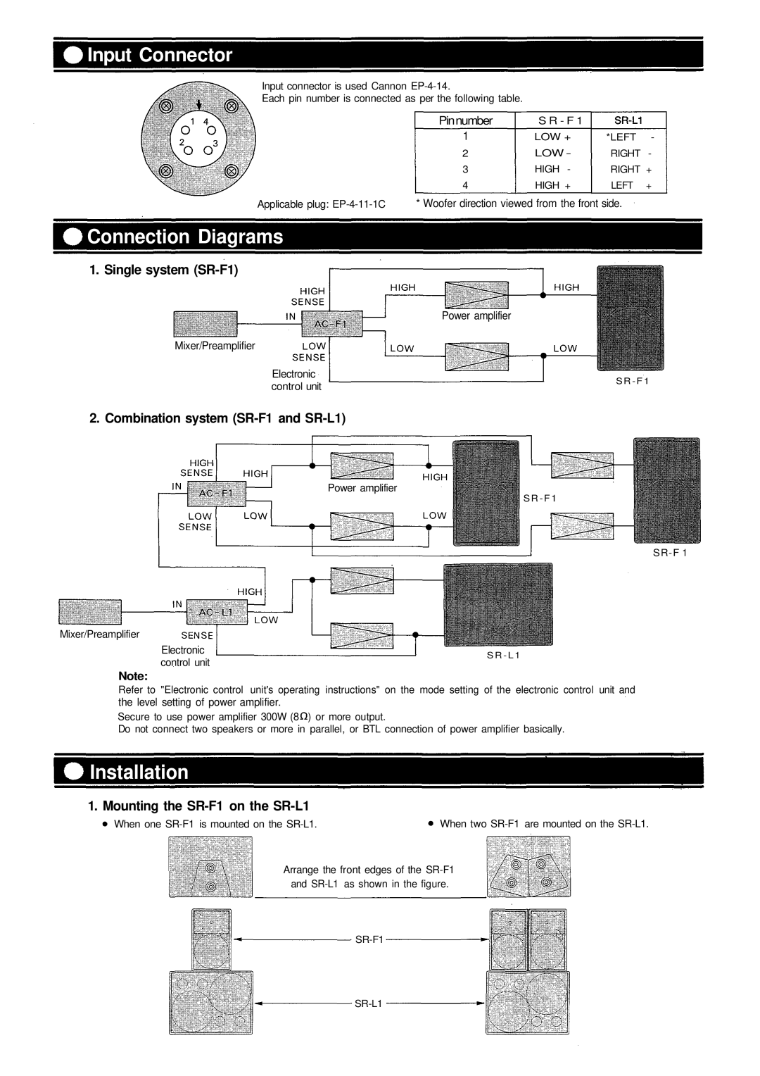
Input connector is used Cannon
Each pin number is connected as per the following table.
Pinnumber | S R - F 1 |
|
| |
1 | LOW + | *LEFT | - | |
2 | LOW - | RIGHT - | ||
3 | HIGH | - | RIGHT + | |
4 | HIGH | + | LEFT | + |
Applicable plug:
Connection Diagrams
1. Single system (SR-F1)
Power amplifier
Mixer/Preamplifier
Electronic
control unit
S R - F 1
2. Combination system (SR-F1 and SR-L1)
Power amplifier
S R - F 1
Mixer/Preamplifier
Electronic | S R - L 1 | |
control unit | ||
|
Note:
Refer to "Electronic control unit's operating instructions" on the mode setting of the electronic control unit and
the level setting of power amplifier.
Secure to use power amplifier 300W (8![]() ) or more output.
) or more output.
Do not connect two speakers or more in parallel, or BTL connection of power amplifier basically.
Installation
1. Mounting the SR-F1 on the SR-L1
When one
When two
Arrange the front edges of the