Getting Connected
Taking a look at the
Signal Path
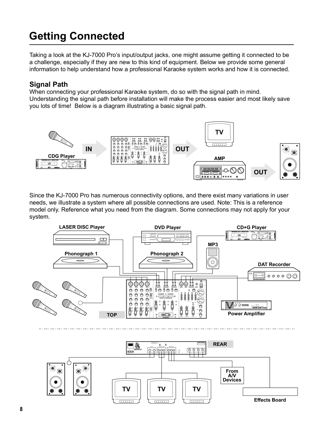
When connecting your professional Karaoke system, do so with the signal path in mind. Understanding the signal path before installation will make the process easier and most likely save you lots of time! Below is a diagram illustrating a basic signal path.
IN
CDG Player
|
|
|
| TV |
b | DIGITAL KEY CONTROLLER | # | OUT | |
|
|
| ||
A/V1 | A/V2 | A/V3 |
| AMP |
| CROSSFADER |
|
| MASTER L MASTER R BOOTH |
|
|
|
| |
OUT
Since the
LASER DISC Player
Phonograph 1
DVD Player
Phonograph 2
CD+G Player
MP3
DAT Recorder
|
|
|
|
| VU METER |
b |
| # |
|
|
|
| DIGITAL KEY CONTROLLER |
|
|
| |
|
|
|
|
| VU METER |
|
|
|
| ECHO |
|
|
|
|
| REPEAT |
|
A/V1 | A/V2 | A/V3 |
|
| Power Amplifier |
TOP |
|
|
| DELAY | |
CROSSFADER | MASTER L MASTER R | BOOTH |
| Digital | |
|
|
| Echo | ||
BOTH
R L
GNDGND
VIDEO 0UTPUT
3 2 1
VIDEO INPUT
3 2 1
SERIAL NUMBERREAR
INSERT INSERT INSERT INSERT
4 | 3 | 2 | 1 |
From
A/V
Devices
TV TV TV
Effects Board
8
