Getting Started
Caution: Before connecting the power supply, make sure that the power switch on the reciever is switched OFF. Note:For additional protection, it is recommended that you plug in the power supply to a surge protector/Power strip.
Setting Up the UHF-388
Set up the
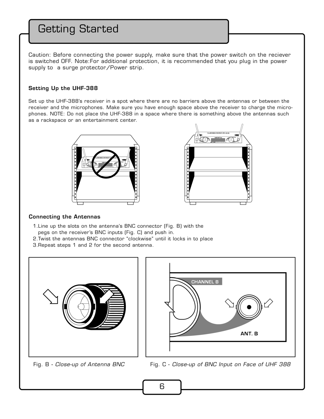
Connecting the Antennas
1.Line up the slots on the antenna’s BNC connector (Fig. B) with the pegs on the receiver’s BNC inputs (Fig. C) and push in.
2.Twist the antennas BNC connector “clockwise” until it locks in to place 3.Repeat steps 1 and 2 for the second antenna.
CHANNEL B
ANT. B
Fig. B - Close-up of Antenna BNC Fig. C - Close-up of BNC Input on Face of UHF 388
6