
VT 1930c specifications
The VTech VT 1930c is an innovative communication device designed to enhance the home phone experience with advanced features and modern technologies. This versatile cordless phone offers a blend of functionality, style, and convenience, making it a valuable addition to any household.One of the standout features of the VT 1930c is its exceptional range, providing users with a robust connection that allows for clear conversations even at distances away from the base unit. This is made possible through DECT (Digital Enhanced Cordless Telecommunications) technology, which ensures interference-free calls and enhances security by using encrypted signals. With DECT technology, you can enjoy enhanced clarity and a reliable connection, free from the disruptions commonly associated with traditional cordless phones.
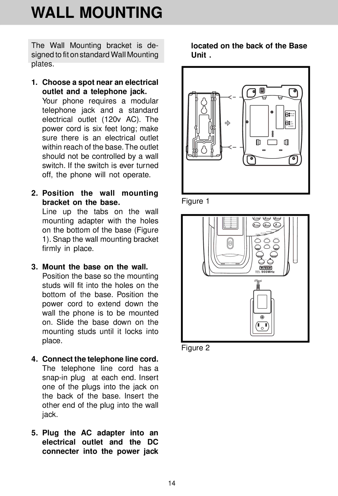
The VTech VT 1930c also comes equipped with a digital answering system that captures messages when users are unavailable to take calls. The answering system has a generous recording capacity, allowing users to save important messages without the fear of running out of space. Additionally, the phone features a user-friendly interface that makes accessing and managing messages easy and intuitive.
Another significant characteristic of the VT 1930c is its large, backlit display. The visually accessible screen provides clear visibility of incoming caller information, making it easy to identify who is calling. This feature, combined with a built-in speakerphone option, enhances the overall user experience, allowing for hands-free conversations.
The phone also includes a number of practical functions such as caller ID and call waiting, which are standard features in modern phones but are often enhanced in VTech devices. Users can easily review missed calls and keep track of who has called without having to rely solely on memory.
Moreover, the VTech VT 1930c is designed with energy efficiency in mind. The device uses eco-friendly technology that reduces power consumption during operation and on standby, making it both economical and environmentally friendly.
Overall, the VTech VT 1930c represents a harmonious blend of advanced technology and user-friendly design. With its impressive range, digital answering capabilities, ease of use, and energy-efficient features, it's an ideal choice for those seeking a reliable and stylish cordless phone for their home.