GAS CONNECTION
Caution: The pipe thread compound used when installing pipes must be a type that is resistant to the action of liquified petroleum or propane gases.
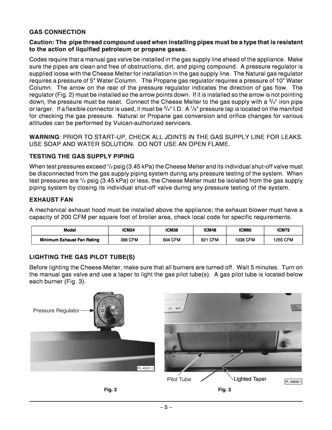
Codes require that a manual gas valve be installed in the gas supply line ahead of the appliance. Make sure the pipes are clean and free of obstructions, dirt, and piping compound. A pressure regulator is supplied loose with the Cheese Melter for installation in the gas supply line. The Natural gas regulator requires a pressure of 5" Water Column. The Propane gas regulator requires a pressure of 10" Water Column. The arrow on the rear of the pressure regulator indicates the direction of gas flow. The regulator (Fig. 2) must be installed so the arrow points down. If it is installed so the arrow is not pointing down, the pressure must be reset. Connect the Cheese Melter to the gas supply with a 3/4" iron pipe or larger. If a flexible connector is used, it must be 3/4" I.D. A 1/8" pressure tap is located on the manifold for checking the gas pressure. Natural or Propane gas conversion and orifice changes for various altitudes can be performed by
WARNING: PRIOR TO
TESTING THE GAS SUPPLY PIPING
When test pressures exceed 1/2 psig (3.45 kPa) the Cheese Melter and its individual
EXHAUST FAN
A mechanical exhaust hood must be installed above the appliance; the exhaust blower must have a capacity of 200 CFM per square foot of broiler area, check local code for specific requirements.
Model | ICM24 | ICM36 | ICM48 | ICM60 | ICM72 |
|
|
|
|
|
|
Minimum Exhaust Fan Rating | 388 CFM | 604 CFM | 821 CFM | 1038 CFM | 1255 CFM |
|
|
|
|
|
|
LIGHTING THE GAS PILOT TUBE(S)
Before lighting the Cheese Melter, make sure that all burners are turned off. Wait 5 minutes. Turn on the manual gas valve and use a taper to light the gas pilot tube(s). A gas pilot tube is located below each burner (Fig. 3).
Pressure Regulator ![]()
| Pilot Tube | Lighted Taper |
Fig. 2 | Fig. 3 | |
– 5 –