P.O. Box 67 Mt. Hope, OH 44660
(888) 827-3667
Radio Receiver
Models: 3990-372, 3994-433
Installation Instructions
and Owner’s Manual
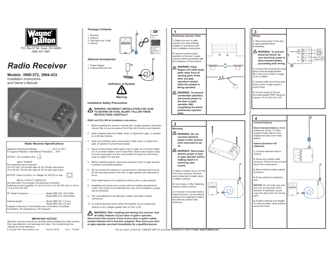
Package Contents:
1.Receiver
2.Antenna
3.Twin-lead wire, 6 feet
4.Manual
Optional Accessories: | 1. | | | | |
1. Power Adapter | | | | | 2. |
2. Antenna Extension Kit | | | | | | |
| | | | | | |
| | | | | | |
Definition of Symbol
Warning
Installation Safety Precautions
WARNING: INCORRECT INSTALLATION CAN LEAD TO SEVERE OR FATAL INJURY. FOLLOW THESE INSTRUCTIONS CAREFULLY.
1
Preliminary Operator Tests:
1.Make sure door or gate operator has been properly installed in accordance with unit’s installation instructions.
2.Test and confi rm proper operation of the door or gate operator before proceeding with the installation of this receiver.
WARNING: Keep
fingers and other body parts away from all moving parts of the door and gate operators system while the system is being operated.
 WARNING: To prevent unintended operation, disconnect power to the door or gate operator after completing the above preliminary operator tests.
3
Wiring:
1.Disconnect power to the door or gate operator before proceeding.
 WARNING: To prevent electrical shock, be sure electrical power is disconnected before proceeding with wiring.
2.Connect the enclosed twin-lead wires to the terminals labeled RLY. (use only 22 AWG or larger; CL2X or better)
3.Connect other end of twin-lead wires to door or gate opener’s control input.
4.Connect power to the two terminals labeled PWR. Receiver requires 10V to 28V AC or DC.
PWR | Power |
NON-POLARIZED | Supply |
PWR | 10V - 28V |
| AC/DC |
RLY | Door or Gate |
|
RLY | control input |
|
Radio Receiver Specifications
Operating Temperature Range:.........................-22 F to 160 F
IP (Ingress Protection, International Protection):.... IP20
NOTICE: Dry Locations Only
INPUT POWER Non-polarized input connection.
10 to 28 VDC, 40 mA with relay off, 60 mA with relay active 10 to 28 VAC, 40 mA with relay off, 90 mA with relay active
NOTICE: Class 2 product, for voltages 32 VAC/DC or less
RELAY OUTPUT CONTACTS Normally-open, dry contacts, non-polarized connection.
Switching current capability:1.0 mA to 0.5 A at 10 to 28 VAC and 2.0 mA to 1.0 A at 10 to 28 VDC
RF Center Frequency: | Model 3990-372, 372.5 MHz. |
| Model 3994-433, 433.92 MHz. |
Antenna length: | Model 3990-372, 7.2 inch |
| Model 3994-433, 5.8 inch |
Capable of learning 14 transmitters (any combination of portable transmitters, RF wall-stations or RF keypads).
IMPORTANT NOTICE!
Read the enclosed instructions carefully before installing this radio receiver. Pay close attention to all warnings and notes. This manual should be retained for future reference.
READ and FOLLOW all installation instructions.
1.Before installing this receiver, read the door or gate operator’s instruction manual fully, so you are aware of all of the unit’s functions and features.
2.Wear protective gloves to install, repair, or adjust door, gate, or operator to avoid hand injuries.
3.Wear eye protection when using tools to install, repair, or adjust door, gate, or operator to prevent eye injuries.
4.Mount control buttons within sight of door or gate, at a minimum height of 5 ft, so small children cannot reach them. Keep control buttons away from all moving parts of a door and at least 6 ft away from all moving parts of a gate or its operator.
5.Before installing receiver, disconnect all power to door or gate operator to prevent unintended operation.
6.Do not connect this receiver to a power source until instructed to do so. Do not reconnect power to the door or gate operator until instructed to do so.
7.Only install receiver on a properly functioning door or gate operator.
8.Installation and wiring must comply with local building and electrical codes. This product is not intended and must not be installed in a explo- sive environment.
9.Pay close attention to all warnings, notices, and notes in these instructions.
10.To prevent electrical shock and/or fi re hazards, do not connect this receiver to any voltages greater than 32 VAC or DC.
WARNING: After installing and testing this receiver, test all safety features of your door or gate’s operator.
Disconnect this receiver if any of your door or gate’s safety system features fail to function properly. Then have your door or gate operator serviced immediately by a qualified person.
2
Mounting:
 WARNING: Do not connect electrical power to this receiver until instructed to do so.
 WARNING: Disconnect electric power to door or gate operator before making repairs or removing case covers.
1.Select a location four to six feet from other receivers. Receiver can be attached to metal, wood, or plastic surfaces.
2.Use screws or other fastening means to attach receiver.
3.If receiver is mounted inside a metal enclosure, use an antenna extension kit (optional) to extend the antenna outside of the enclosure.
4
Connect Antenna:
Direct Connect Antenna: Attach antenna as shown. For best reception keep antenna wire straight and away from metal objects.
Antenna Extension Kit (Optional):
1.Connect extension wire to receiver.
2.Route wire outside metal enclosure. Route and secure wire away from moving parts.
3.Mount antenna holder outside enclosure.
4.Screw antenna to extension wire.
NOTICE: Do not route coax wire near any moving parts of the operator. If necessary, secure coax wire away from any moving parts.
5.Position antenna wire straight. For best reception, keep antenna away from metal.

