2. Hardware Installation and PC Setup
LINE
RESET
CONSOLE DEFAULT LAN 1 LAN 2 LAN 3 LAN 4
Power
POWERSwitch
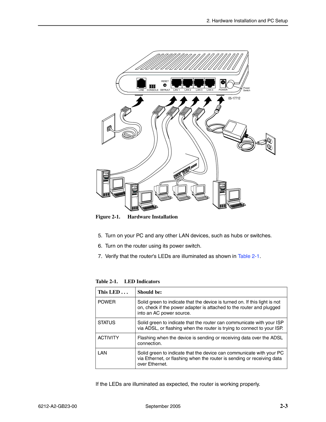
Figure 2-1. Hardware Installation
5.Turn on your PC and any other LAN devices, such as hubs or switches.
6.Turn on the router using its power switch.
7.Verify that the router's LEDs are illuminated as shown in Table
Table 2-1. LED Indicators
This LED . . . | Should be: |
|
|
POWER | Solid green to indicate that the device is turned on. If this light is not |
| on, check if the power adapter is attached to the router and plugged |
| into an AC power source. |
|
|
STATUS | Solid green to indicate that the router can communicate with your ISP |
| via ADSL, or flashing when the router is trying to connect to your ISP. |
|
|
ACTIVITY | Flashing when the device is sending or receiving data over the ADSL |
| connection. |
|
|
LAN | Solid green to indicate that the device can communicate with your PC |
| via Ethernet, or flashing when the router is sending or receiving data |
| over Ethernet. |
|
|
If the LEDs are illuminated as expected, the router is working properly.
September 2005 |