Owner’s Manual.

Note: If you are not installing the idrive® opener on your garage door, you must install the center bracket bushing assembly. Follow these instructions for non-idrive®operated garage doors.

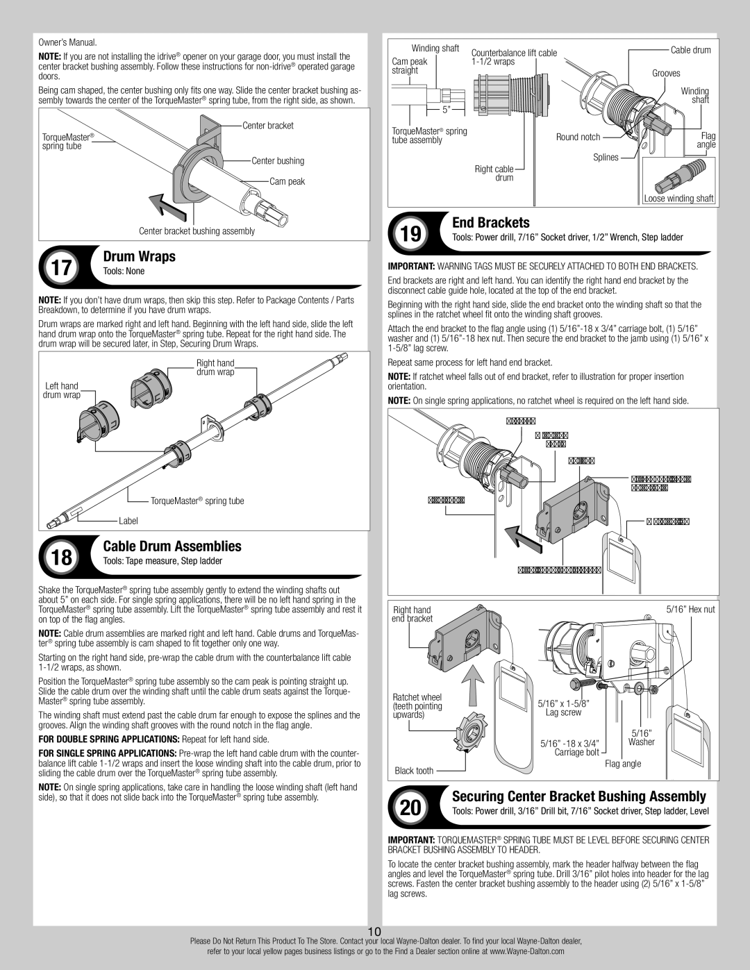
Being cam shaped, the center bushing only fits one way. Slide the center bracket bushing as- sembly towards the center of the TorqueMaster® spring tube, from the right side, as shown.

Center bracket

TorqueMaster® spring tube

Center bushing

Cam peak

Center bracket bushing assembly

17

Drum Wraps

Tools: None

NOTE: If you don’t have drum wraps, then skip this step. Refer to Package Contents / Parts Breakdown, to determine if you have drum wraps.

Drum wraps are marked right and left hand. Beginning with the left hand side, slide the left hand drum wrap onto the TorqueMaster® spring tube. Repeat for the right hand side. The drum wrap will be secured later, in Step, Securing Drum Wraps.

Right hand

drum wrap

Left hand

drum wrap

TorqueMaster® spring tube

Label

18

Cable Drum Assemblies

Tools: Tape measure, Step ladder

Shake the TorqueMaster® spring tube assembly gently to extend the winding shafts out about 5” on each side. For single spring applications, there will be no left hand spring in the TorqueMaster® spring tube assembly. Lift the TorqueMaster® spring tube assembly and rest it on top of the flag angles.

NOTE: Cable drum assemblies are marked right and left hand. Cable drums and TorqueMas- ter® spring tube assembly is cam shaped to fit together only one way.

Starting on the right hand side, pre-wrap the cable drum with the counterbalance lift cable 1-1/2 wraps, as shown.

Position the TorqueMaster® spring tube assembly so the cam peak is pointing straight up. Slide the cable drum over the winding shaft until the cable drum seats against the Torque- Master® spring tube assembly.

The winding shaft must extend past the cable drum far enough to expose the splines and the grooves. Align the winding shaft grooves with the round notch in the flag angle.

For double spring applications: Repeat for left hand side.

For single spring applications: Pre-wrap the left hand cable drum with the counter- balance lift cable 1-1/2 wraps and insert the loose winding shaft into the cable drum, prior to sliding the cable drum over the TorqueMaster® spring tube assembly.

NOTE: On single spring applications, take care in handling the loose winding shaft (left hand side), so that it does not slide back into the TorqueMaster® spring tube assembly.

Winding shaft

Counterbalance lift cable

Cable drum

Cam peak

1-1/2 wraps


straight


Grooves


Winding

5”


shaft


TorqueMaster® spring

Round notch

Flag

tube assembly


angle


Splines


Right cable


drum


Loose winding shaft

19

End Brackets

Tools: Power drill, 7/16” Socket driver, 1/2” Wrench, Step ladder

IMPORTANT: Warning tags must be securely attached to both end brackets.

End brackets are right and left hand. You can identify the right hand end bracket by the disconnect cable guide hole, located at the top of the end bracket.

Beginning with the right hand side, slide the end bracket onto the winding shaft so that the splines in the ratchet wheel fit onto the winding shaft grooves.

Attach the end bracket to the flag angle using (1) 5/16”-18 x 3/4” carriage bolt, (1) 5/16” washer and (1) 5/16”-18 hex nut. Then secure the end bracket to the jamb using (1) 5/16” x 1-5/8” lag screw.

Repeat same process for left hand end bracket.

NOTE: If ratchet wheel falls out of end bracket, refer to illustration for proper insertion orientation.

NOTE: On single spring applications, no ratchet wheel is required on the left hand side.

Grooves

Winding

shaft

Splines

Disconnect cable

guide hole

Flag angle

Warning tag

Right hand end bracket

Right hand


5/16” Hex nut

end bracket


Ratchet wheel

5/16” x 1-5/8”


(teeth pointing


upwards)

Lag screw


5/16”


5/16” -18 x 3/4”

Washer


Carriage bolt


Black tooth


Flag angle


20

Securing Center Bracket Bushing Assembly

Tools: Power drill, 3/16” Drill bit, 7/16” Socket driver, Step ladder, Level

IMPORTANT: TorqueMaster® spring tube must be level before securing center bracket bushing assembly to header.

To locate the center bracket bushing assembly, mark the header halfway between the flag angles and level the TorqueMaster® spring tube. Drill 3/16” pilot holes into header for the lag screws. Fasten the center bracket bushing assembly to the header using (2) 5/16” x 1-5/8” lag screws.

10

Please Do Not Return This Product To The Store. Contact your local Wayne-Dalton dealer. To find your local Wayne-Dalton dealer,

refer to your local yellow pages business listings or go to the Find a Dealer section online at www.Wayne-Dalton.com

Page 10
Image 10
Wayne-Dalton 9700 End Brackets, Drum Wraps, Cable Drum Assemblies, Securing Center Bracket Bushing Assembly

9700 specifications

Wayne-Dalton is a well-known brand in the garage door industry, offering a wide range of models designed for durability, performance, and aesthetic appeal. Among its most popular series are the 9700, 5000, 8000, 9000, and 9800, each equipped with unique features and advanced technologies to meet diverse customer needs.

The Wayne-Dalton 9700 series is known for its combination of strength and insulation. This garage door is manufactured with a three-layer construction providing robust protection against the elements while offering excellent energy efficiency. The insulated steel construction can help maintain interior temperatures, making it ideal for attached garages.

The 5000 series, on the other hand, is designed for a more traditional look combined with modern performance. Featuring a lightweight design, it is made from durable materials that resist rust and corrosion. The 5000 series can be customized with different colors and styles, allowing homeowners to achieve the perfect aesthetic to enhance their property.

Moving on to the 8000 series, this model is designed for commercial applications and residential use where heavy-duty functions are necessary. It is built to withstand extreme weather conditions while providing optimal security with added strength features. The 8000 series offers smooth operation and minimal maintenance requirements, making it a great choice for those seeking reliability.

The 9000 series stands out with its stylish design and sleek finishes. This series offers advanced insulation options, coupled with numerous panel designs that provide a polished and sophisticated look. The 9000 model emphasizes both aesthetics and energy efficiency, making it a favorite among homeowners looking for a beautiful yet functional garage door.

Lastly, the 9800 series is the premium option within Wayne-Dalton’s offerings. This series is characterized by its high insulation value and thermal efficiency, thanks to its innovative construction techniques. The 9800 doors can be customized with numerous panel options and colors, delivering a luxury look while ensuring excellent performance.

In conclusion, Wayne-Dalton’s 9700, 5000, 8000, 9000, and 9800 series garage doors each feature distinctive characteristics and technologies aimed at enhancing durability, security, and aesthetics. Homeowners can find a reliable option within this range that suits their specific requirements, whether they prioritize insulation, style, or heavy-duty functionality. With Wayne-Dalton’s commitment to quality and innovation, these garage doors stand out in today’s market.