Service
.
101
![]() 112
112
![]() 113
113
110*117
TI4731a
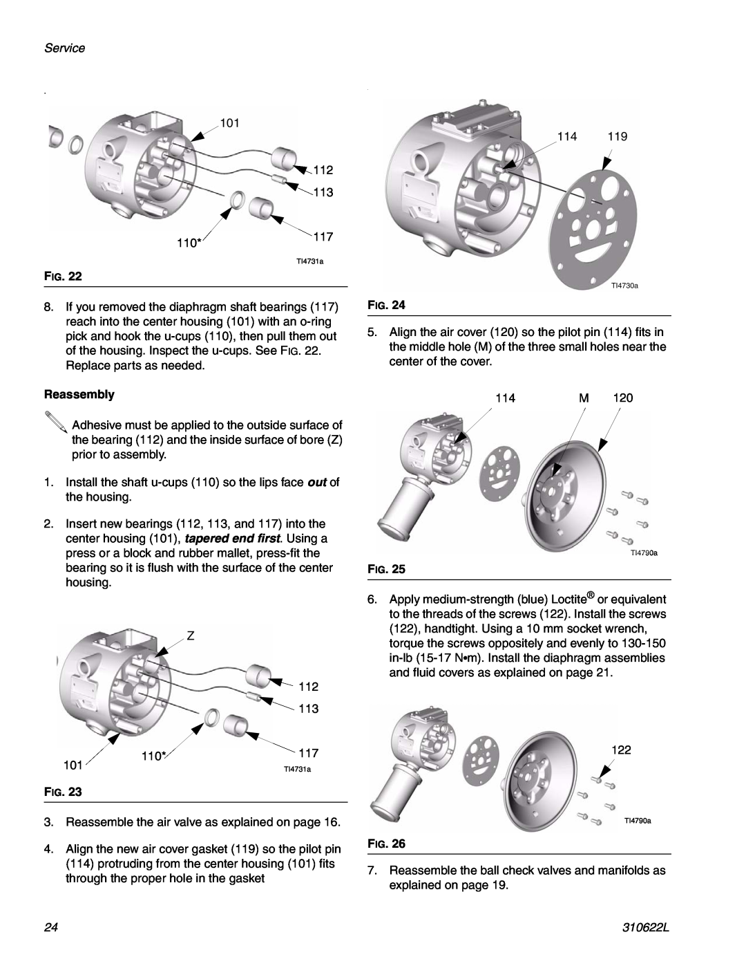
FIG. 22
8.If you removed the diaphragm shaft bearings (117) reach into the center housing (101) with an
Reassembly
![]() Adhesive must be applied to the outside surface of the bearing (112) and the inside surface of bore (Z) prior to assembly.
Adhesive must be applied to the outside surface of the bearing (112) and the inside surface of bore (Z) prior to assembly.
1.Install the shaft
2.Insert new bearings (112, 113, and 117) into the center housing (101), tapered end first. Using a press or a block and rubber mallet,
Z
![]() 112
112
![]() 113
113
110*![]() 117
117
101 | TI4731a |
FIG. 23
3.Reassemble the air valve as explained on page 16.
4.Align the new air cover gasket (119) so the pilot pin (114) protruding from the center housing (101) fits through the proper hole in the gasket
.
114 119
TI4730a
FIG. 24
5.Align the air cover (120) so the pilot pin (114) fits in the middle hole (M) of the three small holes near the center of the cover.
114 | M 120 |
TI4790a
FIG. 25
6.Apply
122
TI4790a
FIG. 26
7.Reassemble the ball check valves and manifolds as explained on page 19.
24 | 310622L |