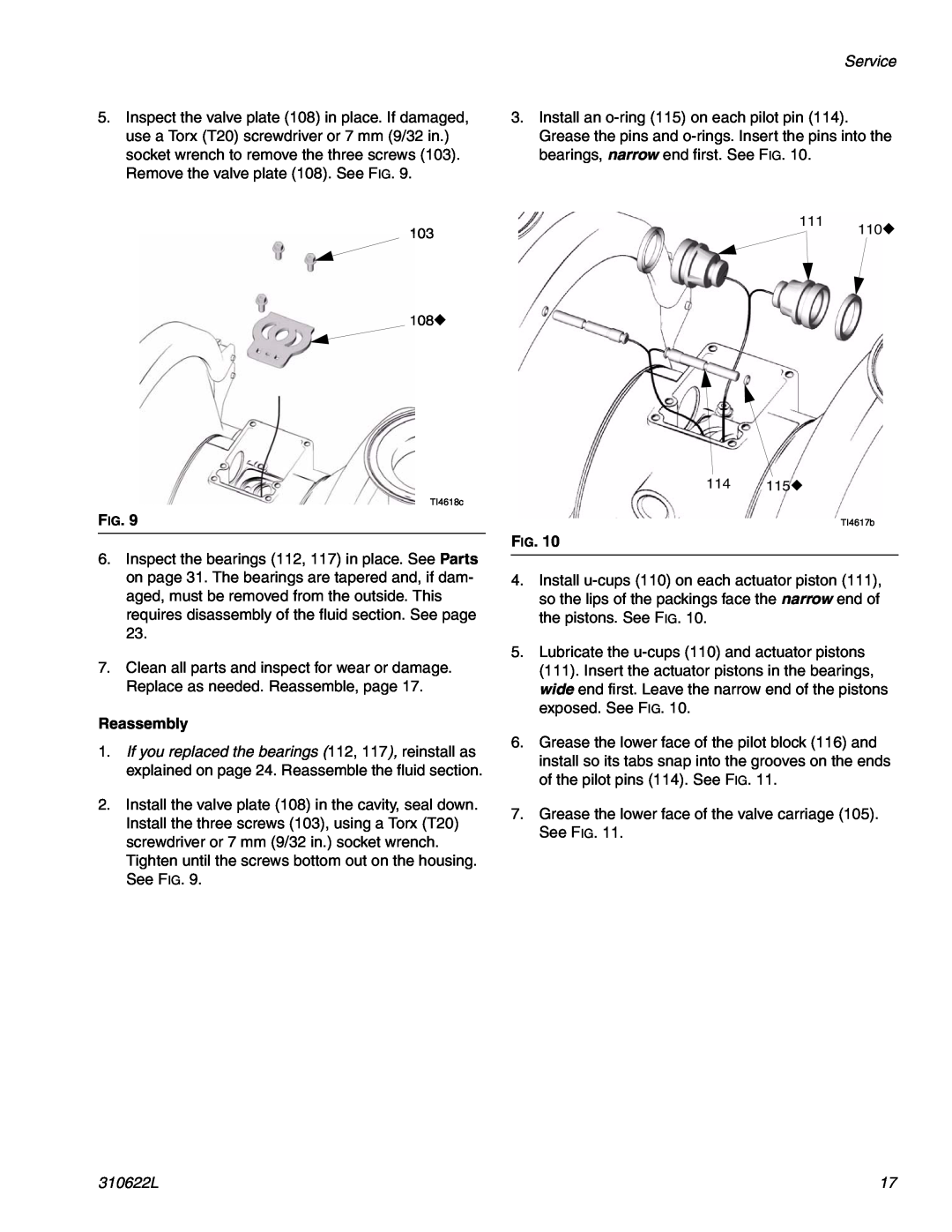
5.Inspect the valve plate (108) in place. If damaged, use a Torx (T20) screwdriver or 7 mm (9/32 in.) socket wrench to remove the three screws (103). Remove the valve plate (108). See FIG. 9.
103
108◆
TI4618c
FIG. 9
6.Inspect the bearings (112, 117) in place. See Parts on page 31. The bearings are tapered and, if dam- aged, must be removed from the outside. This requires disassembly of the fluid section. See page 23.
7.Clean all parts and inspect for wear or damage. Replace as needed. Reassemble, page 17.
Reassembly
1.If you replaced the bearings (112, 117), reinstall as explained on page 24. Reassemble the fluid section.
2.Install the valve plate (108) in the cavity, seal down. Install the three screws (103), using a Torx (T20) screwdriver or 7 mm (9/32 in.) socket wrench. Tighten until the screws bottom out on the housing. See FIG. 9.
Service
3.Install an
111 ◆
110
114 115◆
TI4617b
FIG. 10
4.Install
5.Lubricate the
6.Grease the lower face of the pilot block (116) and install so its tabs snap into the grooves on the ends of the pilot pins (114). See FIG. 11.
7.Grease the lower face of the valve carriage (105). See FIG. 11.
310622L | 17 |