Step 10
Install igniter
Note - The igniter wires are already attached to the Gas Catcher Ignition Chamber and the igniter. This was done to factory test the ignition system.
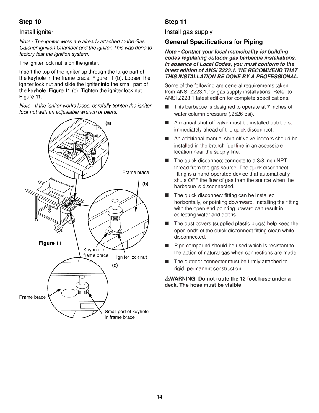
The igniter lock nut is on the igniter.
Insert the top of the igniter up through the large part of the keyhole in the frame brace. Figure 11 (b). Loosen the igniter lock nut and slide the igniter into the small part of the keyhole. Figure 11 (c). Tighten the igniter lock nut. Figure 11.
Note - If the igniter works loose, carefully tighten the igniter lock nut with an adjustable wrench or pliers.
(a)
Frame brace
(b)
Figure 11
Keyhole in |
|
frame brace | Igniter lock nut |
| |
| (c) |
Frame brace ![]()
Small part of keyhole in frame brace
Step 11
Install gas supply
General Specifications for Piping
Note - Contact your local municipality for building codes regulating outdoor gas barbecue installations. In absence of Local Codes, you must conform to the latest edition of ANSI Z223.1. WE RECOMMEND THAT THIS INSTALLATION BE DONE BY A PROFESSIONAL.
Some of the following are general requirements taken from ANSI Z223.1, for gas supply installations. Refer to ANSI Z223.1 latest edition for complete specifications.
■This barbecue is designed to operate at 7 inches of water column pressure (.2526 psi).
■A manual
■An additional manual
■The quick disconnect connects to a 3/8 inch NPT thread from the gas source. The quick disconnect fitting is a
■The quick disconnect fitting can be installed horizontally, or pointing downward. Installing the fitting with the open end pointing upward can result in collecting water and debris.
■The dust covers (supplied plastic plugs) help keep the open ends of the quick disconnect fitting clean while disconnected.
■Pipe compound should be used which is resistant to the action of natural gas when connections are made.
■The outdoor connector must be firmly attached to rigid, permanent construction.
mWARNING: Do not route the 12 foot hose under a deck. The hose must be visible.
14
