Step 4
Continue frame assembly
You will need: frame assembly, front panel, four 1/2 inch bolts, four nylon washers and a 7/16 inch
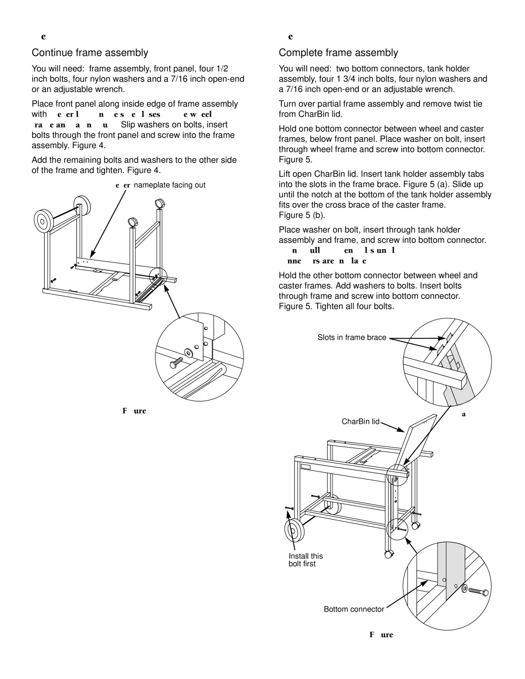
Place front panel along inside edge of frame assembly with Weber logo on the side closest to the wheel frame and facing out. Slip washers on bolts, insert bolts through the front panel and screw into the frame assembly. Figure 4.
Add the remaining bolts and washers to the other side of the frame and tighten. Figure 4.
Weber nameplate facing out
Figure 4
Step 5
Complete frame assembly
You will need: two bottom connectors, tank holder assembly, four 1 3/4 inch bolts, four nylon washers and a 7/16 inch
Turn over partial frame assembly and remove twist tie from CharBin lid.
Hold one bottom connector between wheel and caster frames, below front panel. Place washer on bolt, insert through wheel frame and screw into bottom connector. Figure 5.
Lift open CharBin lid. Insert tank holder assembly tabs into the slots in the frame brace. Figure 5 (a). Slide up until the notch at the bottom of the tank holder assembly fits over the cross brace of the caster frame.
Figure 5 (b).
Place washer on bolt, insert through tank holder assembly and frame, and screw into bottom connector.
Do not fully tighten bolts until both bottom connectors are in place.
Hold the other bottom connector between wheel and caster frames. Add washers to bolts. Insert bolts through frame and screw into bottom connector. Figure 5. Tighten all four bolts.
Slots in frame brace ![]()
(a)
CharBin lid
(b)
Install this bolt first
Bottom connector
Figure 5
11