952711905 specifications
The Weed Eater 952711905 is a versatile and efficient garden tool, designed to tackle a variety of landscaping tasks with ease. As a trimmer, it excels in maintaining lawns, gardens, and various outdoor spaces, making it a popular choice among homeowners and landscape professionals alike.One of the standout features of the Weed Eater 952711905 is its powerful engine, which provides robust performance for trimming through thick grass, weeds, and other overgrowth. This gas-powered trimmer offers a balance of power and efficiency, allowing for longer run times compared to electric models. Users will appreciate its ability to cut through tough vegetation without bogging down, making it ideal for larger yards or areas where heavy-duty trimming is necessary.
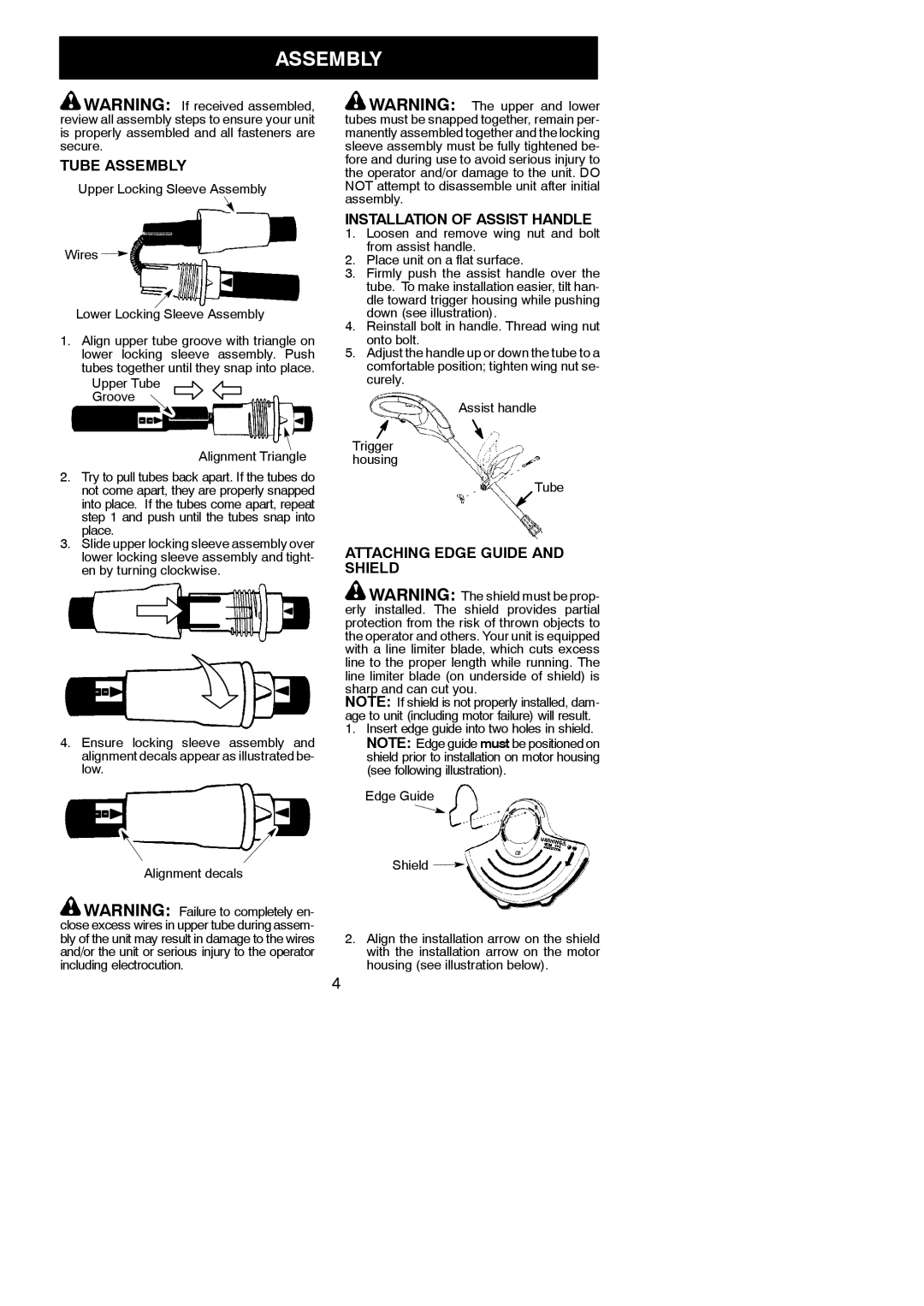
The design of the Weed Eater 952711905 includes a lightweight and ergonomic frame, ensuring that it can be maneuvered easily while minimizing fatigue during extended use. Its adjustable handle allows for comfortable operation at different angles, which is particularly useful when trimming uneven terrain or around flower beds. The overall build quality is robust, designed to withstand the rigors of regular lawn care without compromising performance.
Another significant technology incorporated into the Weed Eater 952711905 is its Easy Start feature, which streamlines the startup process, saving users time and effort. Coupled with this is the inclusion of a reliable bump feed mechanism that automatically dispenses the cutting line as needed, ensuring uninterrupted trimming without the hassle of manual line adjustments.
The trimmer utilizes a dual-line cutting system, enhancing its ability to deliver cleaner cuts and improved efficiency. This technology not only enhances the quality of the cut but also reduces the amount of time spent messing with the trimmer line. Additionally, the cutting width of the Weed Eater 952711905 is expansive, allowing users to cover more ground with each pass.
Maintenance is simplified through easy-access components, ensuring that users can perform routine checks and replacements with minimum hassle. With its combination of power, user-friendly design, and advanced technology, the Weed Eater 952711905 stands out as an efficient tool for keeping outdoor spaces neat and tidy, making it an essential addition to any gardening arsenal.

