4600 specifications
Wegener Communications 4600 is a state-of-the-art digital satellite receiver designed for high-performance applications in the broadcasting and telecommunications sectors. This advanced receiver is part of Wegener's renowned line of products, catering to a range of broadcasting needs, from television to data communications. The Wegener 4600 offers a host of features that make it an attractive choice for both broadcasters and service providers.One of the key features of the Wegener 4600 is its robust satellite reception capability. It supports a wide range of satellite frequencies and protocols, ensuring reliable connectivity in various scenarios. The device is engineered to work seamlessly with the DVB-S and DVB-S2 standards, which allow for efficient compression and transmission of high-definition video content. This ensures that users can deliver high-quality broadcasts with minimal latency, an essential factor in today's fast-paced media landscape.
Another standout characteristic of the Wegener 4600 is its versatile encoding and decoding capabilities. It supports a variety of video and audio codecs, including MPEG-2, MPEG-4, and AAC, among others. This flexibility enables content providers to choose the best formats for their specific needs, enhancing the viewer's experience while optimizing bandwidth usage.
The Wegener 4600 also features advanced management and monitoring capabilities. Through its user-friendly interface, operators can easily configure settings, monitor performance metrics, and manage multiple streams. This functionality is crucial for maintaining optimal performance and ensuring the reliability of the broadcast.
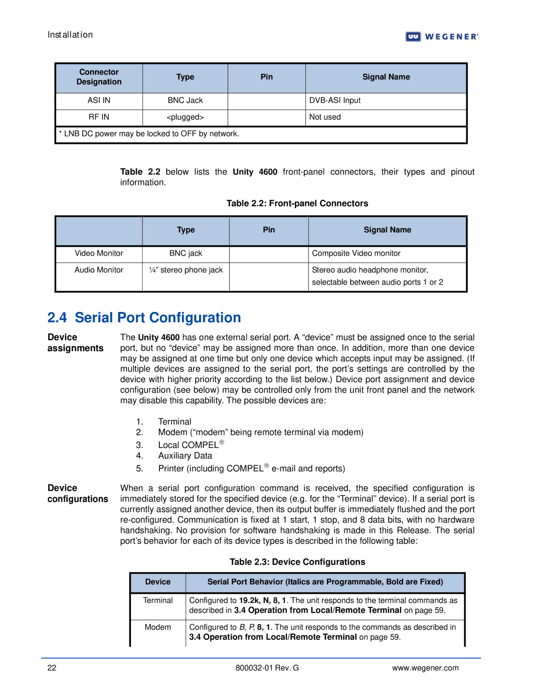
In terms of connectivity, the device supports various interfaces, including ASI and IP, enabling integration with existing broadcast infrastructures. This adaptability is a significant advantage for organizations looking to upgrade or expand their capabilities without extensive redesigns of their current systems.
Security is another key aspect of the Wegener 4600. It incorporates robust encryption options that protect content from unauthorized access and piracy. This feature is increasingly important as the demand for secure transmission of sensitive data grows.
Overall, Wegener Communications 4600 stands out in the crowded market of digital satellite receivers. With its combination of superior reception capabilities, versatile encoding options, advanced management features, and strong security protocols, it represents an ideal solution for broadcasters and telecommunications providers seeking to enhance their service offerings and deliver high-quality content to viewers worldwide.

