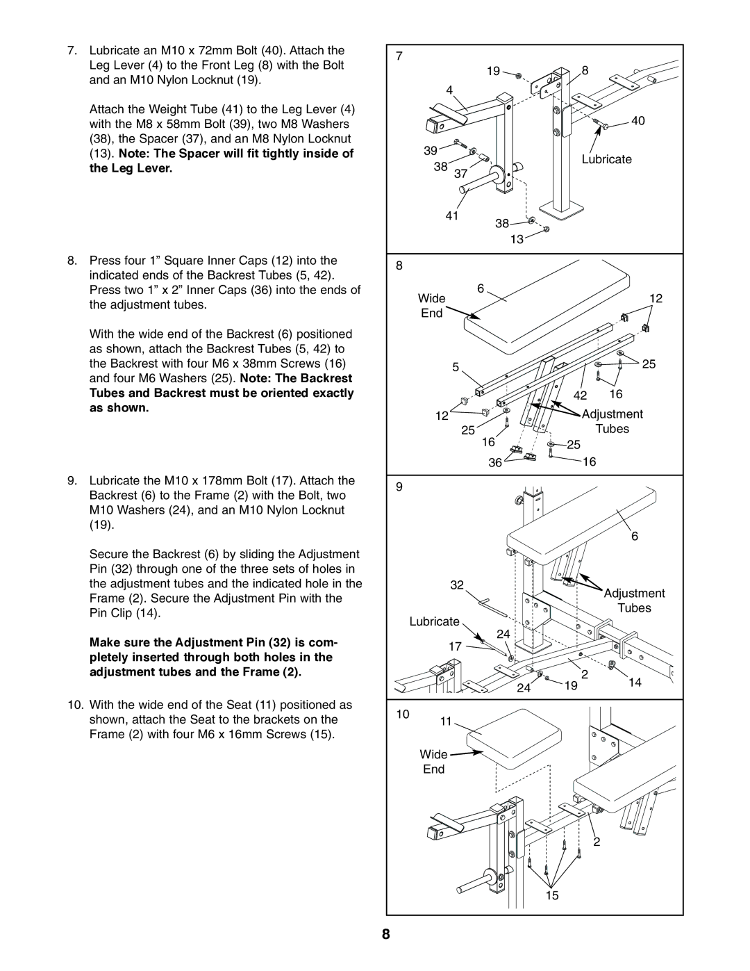
7. | Lubricate an M10 x 72mm Bolt (40). Attach the | 7 |
|
|
|
|
|
| Leg Lever (4) to the Front Leg (8) with the Bolt |
|
|
|
|
| |
|
|
|
| 19 | 8 |
| |
| and an M10 Nylon Locknut (19). |
|
|
|
| ||
|
| 4 |
|
|
| ||
|
|
|
|
|
| ||
| Attach the Weight Tube (41) to the Leg Lever (4) |
|
|
|
|
| 40 |
| with the M8 x 58mm Bolt (39), two M8 Washers |
|
|
|
|
| |
| (38), the Spacer (37), and an M8 Nylon Locknut |
| 39 |
|
|
|
|
| (13). Note: The Spacer will fit tightly inside of |
|
|
| Lubricate | ||
| the Leg Lever. |
| 38 |
|
| ||
|
| 37 |
|
|
| ||
|
|
|
|
|
|
| |
|
|
| 41 | 38 |
|
| |
|
|
|
|
|
|
| |
|
|
|
|
| 13 |
|
|
8. | Press four 1” Square Inner Caps (12) into the | 8 |
|
|
|
|
|
| indicated ends of the Backrest Tubes (5, 42). |
|
|
|
|
| |
|
|
|
| 6 |
|
| |
| Press two 1” x 2” Inner Caps (36) into the ends of |
| Wide |
|
| 12 | |
| the adjustment tubes. |
|
|
|
| ||
|
| End |
|
|
|
| |
|
|
|
|
|
|
| |
| With the wide end of the Backrest (6) positioned |
|
|
|
|
|
|
| as shown, attach the Backrest Tubes (5, 42) to |
|
|
|
|
|
|
| the Backrest with four M6 x 38mm Screws (16) |
|
| 5 |
|
| 25 |
| and four M6 Washers (25). Note: The Backrest |
|
|
|
|
|
|
| Tubes and Backrest must be oriented exactly |
|
|
|
| 42 | 16 |
| as shown. |
| 12 |
| Adjustment | ||
|
|
|
| ||||
|
|
|
| 25 | 16 |
| Tubes |
|
|
|
|
| 25 |
| |
|
|
|
|
| 36 | 16 | |
9. | Lubricate the M10 x 178mm Bolt (17). Attach the | 9 |
|
|
|
|
|
| Backrest (6) to the Frame (2) with the Bolt, two |
|
|
|
|
| |
|
|
|
|
|
|
| |
| M10 Washers (24), and an M10 Nylon Locknut |
|
|
|
|
|
|
| (19). |
|
|
|
|
| 6 |
|
|
|
|
|
|
| |
| Secure the Backrest (6) by sliding the Adjustment |
|
|
|
|
|
|
| Pin (32) through one of the three sets of holes in |
|
|
|
|
|
|
| the adjustment tubes and the indicated hole in the |
|
| 32 |
|
| Adjustment |
| Frame (2). Secure the Adjustment Pin with the |
|
|
|
|
| |
|
|
|
|
|
| Tubes | |
| Pin Clip (14). |
| Lubricate |
|
| ||
|
|
|
|
| |||
|
|
| 24 |
|
| ||
| Make sure the Adjustment Pin (32) is com- |
|
| 17 |
|
| |
|
|
|
|
|
| ||
| pletely inserted through both holes in the |
|
|
|
|
| |
|
|
|
|
|
|
| |
| adjustment tubes and the Frame (2). |
|
|
|
| 2 | 14 |
|
|
|
|
| 24 | 19 | |
10. | With the wide end of the Seat (11) positioned as | 10 |
|
|
|
|
|
| shown, attach the Seat to the brackets on the | 11 |
|
|
| ||
|
|
|
|
| |||
| Frame (2) with four M6 x 16mm Screws (15). |
|
|
|
|
|
|
|
|
| Wide |
|
|
|
|
|
|
| End |
|
|
|
|
|
|
|
|
|
|
| 2 |
|
|
|
|
|
| 15 |
|
|
| 8 |
|
|
|
|
|