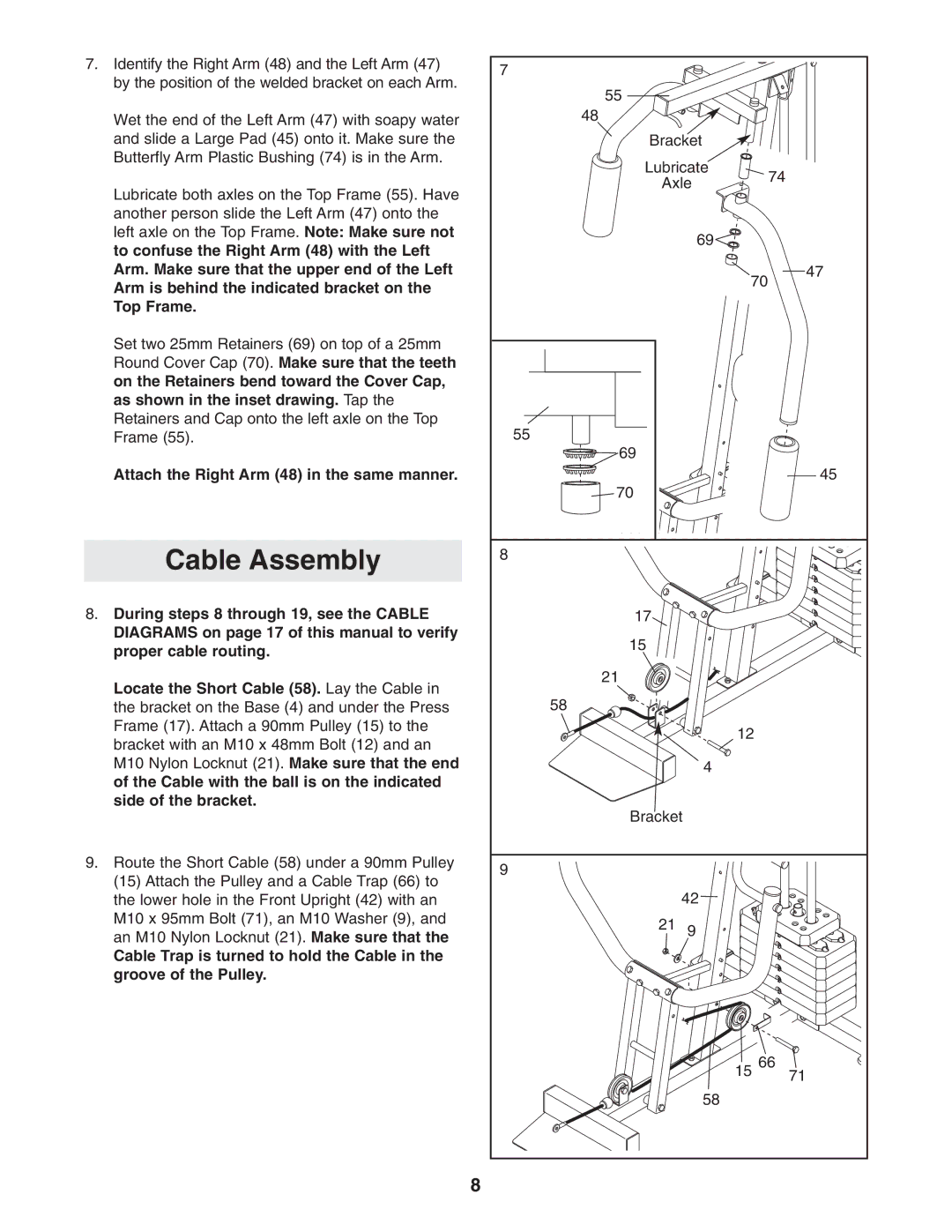
7.Identify the Right Arm (48) and the Left Arm (47) by the position of the welded bracket on each Arm.
Wet the end of the Left Arm (47) with soapy water and slide a Large Pad (45) onto it. Make sure the Butterfly Arm Plastic Bushing (74) is in the Arm.
Lubricate both axles on the Top Frame (55). Have another person slide the Left Arm (47) onto the left axle on the Top Frame. Note: Make sure not to confuse the Right Arm (48) with the Left Arm. Make sure that the upper end of the Left Arm is behind the indicated bracket on the Top Frame.
Set two 25mm Retainers (69) on top of a 25mm Round Cover Cap (70). Make sure that the teeth on the Retainers bend toward the Cover Cap, as shown in the inset drawing. Tap the Retainers and Cap onto the left axle on the Top Frame (55).
Attach the Right Arm (48) in the same manner.
Cable Assembly
8.During steps 8 through 19, see the CABLE DIAGRAMS on page 17 of this manual to verify proper cable routing.
Locate the Short Cable (58). Lay the Cable in the bracket on the Base (4) and under the Press Frame (17). Attach a 90mm Pulley (15) to the bracket with an M10 x 48mm Bolt (12) and an M10 Nylon Locknut (21). Make sure that the end of the Cable with the ball is on the indicated side of the bracket.
9.Route the Short Cable (58) under a 90mm Pulley (15) Attach the Pulley and a Cable Trap (66) to the lower hole in the Front Upright (42) with an M10 x 95mm Bolt (71), an M10 Washer (9), and an M10 Nylon Locknut (21). Make sure that the
Cable Trap is turned to hold the Cable in the groove of the Pulley.
8
7 |
|
|
|
55 |
|
|
|
48 |
|
|
|
Bracket |
|
| |
Lubricate | 74 |
| |
Axle |
| ||
|
| ||
| 69 |
|
|
| 70 | 47 | |
|
| ||
55 |
|
|
|
69 |
|
|
|
|
|
| 45 |
70 |
|
|
|
8 |
|
|
|
17 |
|
|
|
15 |
|
|
|
21 |
|
|
|
58 |
|
|
|
| 12 |
|
|
| 4 |
|
|
Bracket |
|
| |
9 |
|
|
|
| 42 |
|
|
21 | 9 |
|
|
| 15 | 66 | 71 |
|
|
| |
| 58 |
|
|