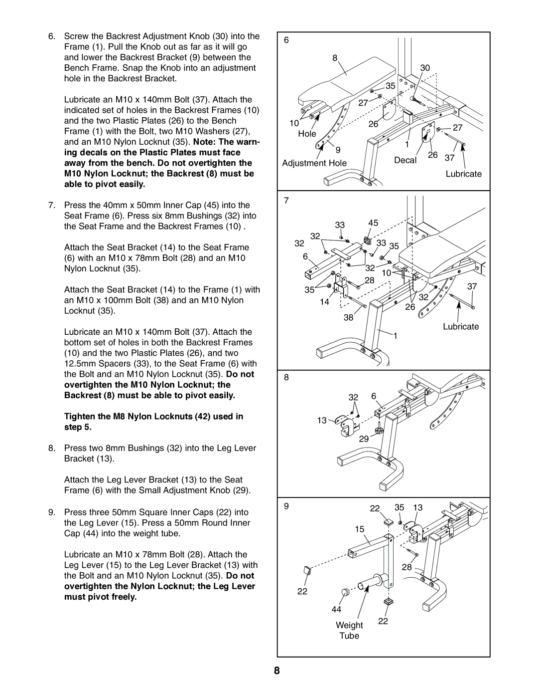
6. Screw the Backrest Adjustment Knob (30) into the | 6 |
|
|
|
|
|
Frame (1). Pull the Knob out as far as it will go |
|
|
|
|
| |
|
|
|
|
|
| |
and lower the Backrest Bracket (9) between the | 8 |
|
|
|
|
|
Bench Frame. Snap the Knob into an adjustment |
|
|
|
| 30 |
|
hole in the Backrest Bracket. |
|
| 35 |
|
|
|
|
|
|
|
|
| |
Lubricate an M10 x 140mm Bolt (37). Attach the | 27 |
|
|
|
| |
indicated set of holes in the Backrest Frames (10) |
|
|
|
| ||
|
|
|
|
|
| |
and the two Plastic Plates (26) to the Bench | 10 | 26 |
|
|
| 27 |
Frame (1) with the Bolt, two M10 Washers (27), |
|
|
| |||
Hole |
|
|
|
| ||
|
|
|
|
| ||
and an M10 Nylon Locknut (35). Note: The warn- |
|
|
|
|
| |
9 |
|
| 1 |
|
| |
ing decals on the Plastic Plates must face |
|
|
|
| ||
| Decal | 26 | 37 | |||
away from the bench. Do not overtighten the | Adjustment Hole |
| ||||
|
|
| ||||
M10 Nylon Locknut; the Backrest (8) must be |
|
|
|
|
| Lubricate |
able to pivot easily. |
|
|
|
|
|
|
7. Press the 40mm x 50mm Inner Cap (45) into the | 7 |
|
|
|
|
|
|
|
|
|
|
| |
Seat Frame (6). Press six 8mm Bushings (32) into | 33 | 45 |
|
|
|
|
the Seat Frame and the Backrest Frames (10) . |
|
|
|
| ||
| 32 | 33 35 |
|
|
| |
Attach the Seat Bracket (14) to the Seat Frame | 32 |
|
|
| ||
(6) with an M10 x 78mm Bolt (28) and an M10 | 6 | 32 |
|
|
|
|
Nylon Locknut (35). |
| 10 |
|
|
| |
Attach the Seat Bracket (14) to the Frame (1) with | 35 | 28 |
|
|
| 37 |
|
|
|
| |||
|
|
| 32 |
| ||
an M10 x 100mm Bolt (38) and an M10 Nylon | 14 |
|
| 26 |
| |
|
|
|
| |||
Locknut (35). |
|
|
|
|
| |
38 |
|
|
|
|
| |
|
|
|
|
| Lubricate | |
Lubricate an M10 x 140mm Bolt (37). Attach the |
|
| 1 |
|
| |
|
|
|
|
| ||
bottom set of holes in both the Backrest Frames |
|
|
|
|
| |
|
|
|
|
|
| |
(10) and the two Plastic Plates (26), and two |
|
|
|
|
|
|
12.5mm Spacers (33), to the Seat Frame (6) with |
|
|
|
|
|
|
the Bolt and an M10 Nylon Locknut (35). Do not | 8 |
|
|
|
|
|
overtighten the M10 Nylon Locknut; the |
|
|
|
|
| |
|
|
|
|
|
| |
Backrest (8) must be able to pivot easily. | 32 | 6 |
|
|
|
|
Tighten the M8 Nylon Locknuts (42) used in | 13 |
|
|
|
|
|
step 5. |
|
|
|
|
| |
|
|
|
|
|
| |
8. Press two 8mm Bushings (32) into the Leg Lever | 29 |
|
|
|
| |
|
|
|
|
|
| |
Bracket (13). |
|
|
|
|
|
|
Attach the Leg Lever Bracket (13) to the Seat |
|
|
|
|
|
|
Frame (6) with the Small Adjustment Knob (29). |
|
|
|
|
|
|
9. Press three 50mm Square Inner Caps (22) into | 9 | 22 | 35 | 13 |
| |
|
|
|
|
|
| |
the Leg Lever (15). Press a 50mm Round Inner | 15 |
|
|
|
|
|
Cap (44) into the weight tube. |
|
|
|
|
| |
|
|
|
|
|
| |
Lubricate an M10 x 78mm Bolt (28). Attach the |
|
|
|
|
|
|
Leg Lever (15) to the Leg Lever Bracket (13) with |
|
| 28 |
|
| |
the Bolt and an M10 Nylon Locknut (35). Do not |
|
|
|
|
|
|
overtighten the Nylon Locknut; the Leg Lever | 22 |
|
|
|
|
|
must pivot freely. |
|
|
|
|
| |
|
|
|
|
|
| |
| 44 |
|
|
|
|
|
| Weight | 22 |
|
|
| |
|
|
|
|
|
| |
| Tube |
|
|
|
|
|
| 8 |
|
|
|
|
|
