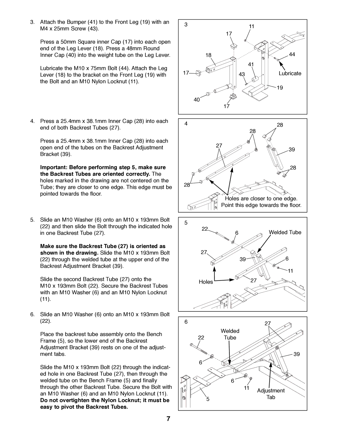
3.Attach the Bumper (41) to the Front Leg (19) with an M4 x 25mm Screw (43).
Press a 50mm Square inner Cap (17) into each open end of the Leg Lever (18). Press a 48mm Round Inner Cap (40) into the weight tube on the Leg Lever.
Lubricate the M10 x 75mm Bolt (44). Attach the Leg Lever (18) to the bracket on the Front Leg (19) with the Bolt and an M10 Nylon Locknut (11).
4.Press a 25.4mm x 38.1mm Inner Cap (28) into each end of both Backrest Tubes (27).
Press a 25.4mm x 38.1mm Inner Cap (28) into each open end of the tubes on the Backrest Adjustment Bracket (39).
Important: Before performing step 5, make sure the Backrest Tubes are oriented correctly. The holes marked in the drawing are not centered on the Tube; they are closer to one edge. This edge must be pointed towards the floor.
3 |
| 11 |
|
| |
| 17 |
|
| 18 | 44 |
|
| 41 |
17 | 43 | Lubricate |
|
| 19 |
| 40 |
|
| 17 |
|
4 |
| 28 |
|
| 28 |
| 27 | 39 |
|
| |
|
| 28 |
28 |
|
|
Holes are closer to one edge.
Point this edge towards the floor.
5.Slide an M10 Washer (6) onto an M10 x 193mm Bolt (22) and then slide the Bolt through the indicated hole in one Backrest Tube (27).
Make sure the Backrest Tube (27) is oriented as shown in the drawing. Slide the M10 x 193mm Bolt
(22)through the welded tube at the upper end of the Backrest Adjustment Bracket (39).
Slide the second Backrest Tube (27) onto the
M10 x 193mm Bolt (22). Secure the Backrest Tubes with an M10 Washer (6) and an M10 Nylon Locknut (11).
6.Slide an M10 Washer (6) onto an M10 x 193mm Bolt (22).
Place the backrest tube assembly onto the Bench Frame (5), so the lower end of the Backrest Adjustment Bracket (39) rests on one of the adjust- ment tabs.
Slide the M10 x 193mm Bolt (22) through the indicat- ed hole in one Backrest Tube (27), then through the welded tube on the Bench Frame (5) and finally through the other Backrest Tube. Secure the Bolt with an M10 Washer (6) and an M10 Nylon Locknut (11).
Do not overtighten the Nylon Locknut; it must be easy to pivot the Backrest Tubes.
7
5 |
|
|
22 | 6 | Welded Tube |
| ||
27 |
| 6 |
| 39 | |
|
| 11 |
Holes |
| 27 |
6 |
| 27 |
|
| |
| Welded |
|
22 | Tube |
|
|
| 39 |
6 |
|
|
| 6 |
|
| 11 | Adjustment |
|
| |
5 |
| Tab |
|
|
