SEAT ASSEMBLY | 49 |
|
|
|
|
|
|
|
|
| |
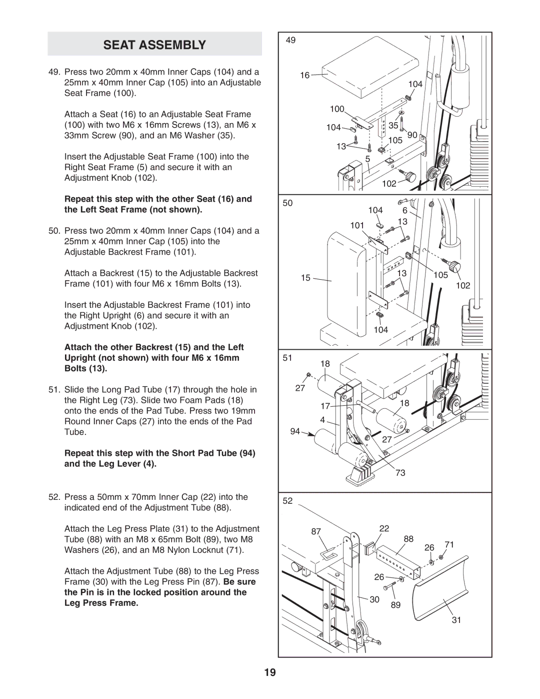
49. Press two 20mm x 40mm Inner Caps (104) and a | 16 |
|
|
|
|
25mm x 40mm Inner Cap (105) into an Adjustable |
| 104 |
|
| |
|
|
|
| ||
Seat Frame (100). |
|
|
|
|
|
Attach a Seat (16) to an Adjustable Seat Frame | 100 |
|
|
|
|
|
|
|
|
| |
(100) with two M6 x 16mm Screws (13), an M6 x | 104 |
| 35 |
|
|
33mm Screw (90), and an M6 Washer (35). | 13 |
| 105 90 |
|
|
|
|
|
|
| |
Insert the Adjustable Seat Frame (100) into the |
| 5 |
|
|
|
Right Seat Frame (5) and secure it with an |
|
|
|
|
|
Adjustment Knob (102). |
| 102 |
|
| |
|
|
|
| ||
Repeat this step with the other Seat (16) and | 50 |
|
|
|
|
the Left Seat Frame (not shown). | 104 | 6 |
|
| |
|
|
| |||
50. Press two 20mm x 40mm Inner Caps (104) and a |
| 101 | 13 |
|
|
|
|
|
| ||
|
|
|
|
| |
25mm x 40mm Inner Cap (105) into the |
|
|
|
|
|
Adjustable Backrest Frame (101). |
|
|
|
|
|
Attach a Backrest (15) to the Adjustable Backrest | 15 |
| 13 | 105 | |
Frame (101) with four M6 x 16mm Bolts (13). |
|
|
| 102 | |
|
|
|
| ||
Insert the Adjustable Backrest Frame (101) into |
|
|
|
|
|
the Right Upright (6) and secure it with an |
|
|
|
|
|
Adjustment Knob (102). |
| 104 |
|
| |
|
|
|
| ||
Attach the other Backrest (15) and the Left |
|
|
|
|
|
Upright (not shown) with four M6 x 16mm | 51 |
|
|
|
|
Bolts (13). | 18 |
|
|
|
|
|
|
|
|
| |
51. Slide the Long Pad Tube (17) through the hole in | 27 |
|
|
|
|
the Right Leg (73). Slide two Foam Pads (18) | 17 |
| 18 |
|
|
onto the ends of the Pad Tube. Press two 19mm |
|
|
| ||
|
|
|
| ||
4 |
|
|
|
| |
Round Inner Caps (27) into the ends of the Pad |
|
|
|
| |
Tube. | 94 | 27 |
|
| |
|
|
|
| ||
Repeat this step with the Short Pad Tube (94) |
|
|
|
|
|
and the Leg Lever (4). |
|
| 73 |
|
|
|
|
|
|
| |
52. Press a 50mm x 70mm Inner Cap (22) into the | 52 |
|
|
|
|
indicated end of the Adjustment Tube (88). |
|
|
|
| |
|
|
|
|
| |
Attach the Leg Press Plate (31) to the Adjustment | 87 | 22 |
|
| |
Tube (88) with an M8 x 65mm Bolt (89), two M8 |
| 88 |
|
| |
|
| 26 | 71 | ||
Washers (26), and an M8 Nylon Locknut (71). |
|
|
| ||
|
|
|
| ||
Attach the Adjustment Tube (88) to the Leg Press |
| 26 |
|
|
|
Frame (30) with the Leg Press Pin (87). Be sure |
|
|
|
| |
|
|
|
|
| |
the Pin is in the locked position around the |
| 30 |
|
|
|
Leg Press Frame. |
| 89 |
|
| |
|
|
|
| ||
|
|
|
|
| 31 |
| 19 |
|
|
|
|