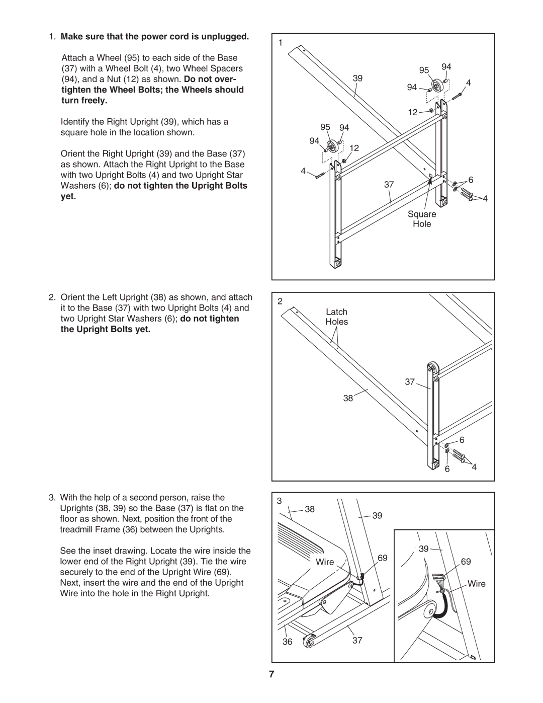
1. Make sure that the power cord is unplugged. | 1 |
|
|
|
|
|
|
|
|
| |
Attach a Wheel (95) to each side of the Base |
|
|
| 94 |
|
(37) with a Wheel Bolt (4), two Wheel Spacers |
|
| 95 |
| |
(94), and a Nut (12) as shown. Do not over- |
|
| 39 |
| 4 |
tighten the Wheel Bolts; the Wheels should |
|
| 94 |
| |
|
|
|
| ||
turn freely. |
|
|
|
|
|
Identify the Right Upright (39), which has a |
|
| 12 |
|
|
| 95 | 94 |
|
| |
square hole in the location shown. |
|
|
| ||
| 94 |
|
|
| |
|
| 12 |
|
| |
Orient the Right Upright (39) and the Base (37) |
|
|
|
| |
|
|
|
|
| |
as shown. Attach the Right Upright to the Base |
| 4 |
|
|
|
with two Upright Bolts (4) and two Upright Star |
|
|
| 6 | |
|
| 37 |
| ||
Washers (6); do not tighten the Upright Bolts |
|
|
| ||
|
|
|
| ||
yet. |
|
|
|
| 4 |
|
|
| Square |
|
|
|
|
| Hole |
|
|
2. Orient the Left Upright (38) as shown, and attach | 2 |
|
|
|
|
it to the Base (37) with two Upright Bolts (4) and |
|
|
|
| |
| Latch |
|
| ||
two Upright Star Washers (6); do not tighten |
|
|
| ||
| Holes |
|
| ||
the Upright Bolts yet. |
|
|
| ||
|
|
|
|
| |
|
|
| 37 |
|
|
|
|
| 38 |
|
|
|
|
|
|
| 6 |
|
|
|
| 6 | 4 |
3. With the help of a second person, raise the | 3 |
|
|
|
|
Uprights (38, 39) so the Base (37) is flat on the | 38 |
|
|
| |
| 39 |
|
| ||
floor as shown. Next, position the front of the |
|
|
|
| |
|
|
|
|
| |
treadmill Frame (36) between the Uprights. |
|
|
|
|
|
See the inset drawing. Locate the wire inside the |
|
| 39 |
|
|
lower end of the Right Upright (39). Tie the wire |
| Wire | 69 |
| 69 |
|
|
| |||
securely to the end of the Upright Wire (69). |
|
|
|
|
|
Next, insert the wire and the end of the Upright |
|
|
|
| Wire |
Wire into the hole in the Right Upright. |
|
|
|
|
|
| 36 |
| 37 |
|
|
| 7 |
|
|
|
|
