ASSEMBLY
Assembly requires two people.Due to the size and
weight of the weight system, assemble it in the loca- tion where it will be used.
•Place all parts of the weight system in a cleared area and remove the packing materials; do not dispose of the packing materials until assembly is completed.
•Before beginning, read each assembly step and
look at each drawing carefully.
•For help identifying small parts used in assembly, refer to the PART CHART attached to the center
of this owner's manual.
•As you assemble the weight system, be sure that all parts are oriented as shown in the drawings.
•Tighten all parts as you attach them, unless instructed to do otherwise.
THE FOLLOWING TOOLS (NOT INCLUDED) ARE
REQUIRED FOR ASSEMBLY:
• Two (2) adjustable wrenches
• One (1) phillips screwdriver
• One (1) rubber mallet
•Lubricant, such as grease or petroleum jelly, and soapy water are also required.
To simplify assembly, the following tools are recom- mended: A socket set, open or closed wrenches, or ratchet wrenches.
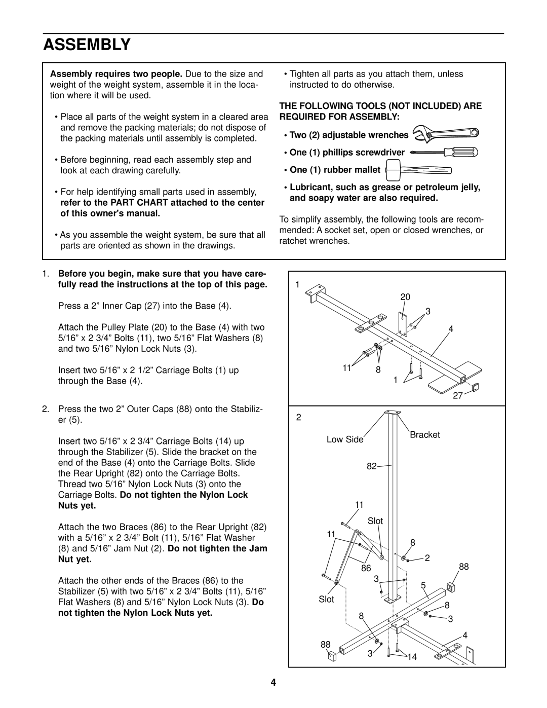
1.Before you begin, make sure that you have care- fully read the instructions at the top of this page.
Press a 2” Inner Cap (27) into the Base (4).
Attach the Pulley Plate (20) to the Base (4) with two 5/16” x 2 3/4” Bolts (11), two 5/16” Flat Washers (8) and two 5/16” Nylon Lock Nuts (3).
Insert two 5/16” x 2 1/2” Carriage Bolts (1) up through the Base (4).
2.Press the two 2” Outer Caps (88) onto the Stabiliz-
er (5).
Insert two 5/16” x 2 3/4” Carriage Bolts (14) up through the Stabilizer (5). Slide the bracket on the end of the Base (4) onto the Carriage Bolts. Slide the Rear Upright (82) onto the Carriage Bolts. Thread two 5/16” Nylon Lock Nuts (3) onto the Carriage Bolts. Do not tighten the Nylon Lock
Nuts yet.
Attach the two Braces (86) to the Rear Upright (82) with a 5/16” x 2 3/4” Bolt (11), 5/16” Flat Washer
(8)and 5/16” Jam Nut (2). Do not tighten the Jam
Nut yet.
Attach the other ends of the Braces (86) to the
Stabilizer (5) with two 5/16” x 2 3/4” Bolts (11), 5/16”
Flat Washers (8) and 5/16” Nylon Lock Nuts (3). Do not tighten the Nylon Lock Nuts yet.
1 |
|
|
|
| 20 |
|
| 3 |
|
| 4 |
11 | 8 |
|
|
| 1 |
|
| 27 |
2 |
|
|
Low Side |
| Bracket |
|
| |
82 |
| |
11 |
|
|
| Slot |
|
11 |
| 8 |
|
| |
|
| 2 |
86 |
| 88 |
| 3 | 5 |
|
| |
Slot |
| 8 |
|
| |
8 |
| 3 |
|
| |
88 |
| 4 |
3 |
| |
| 14 | |
|
| |
4