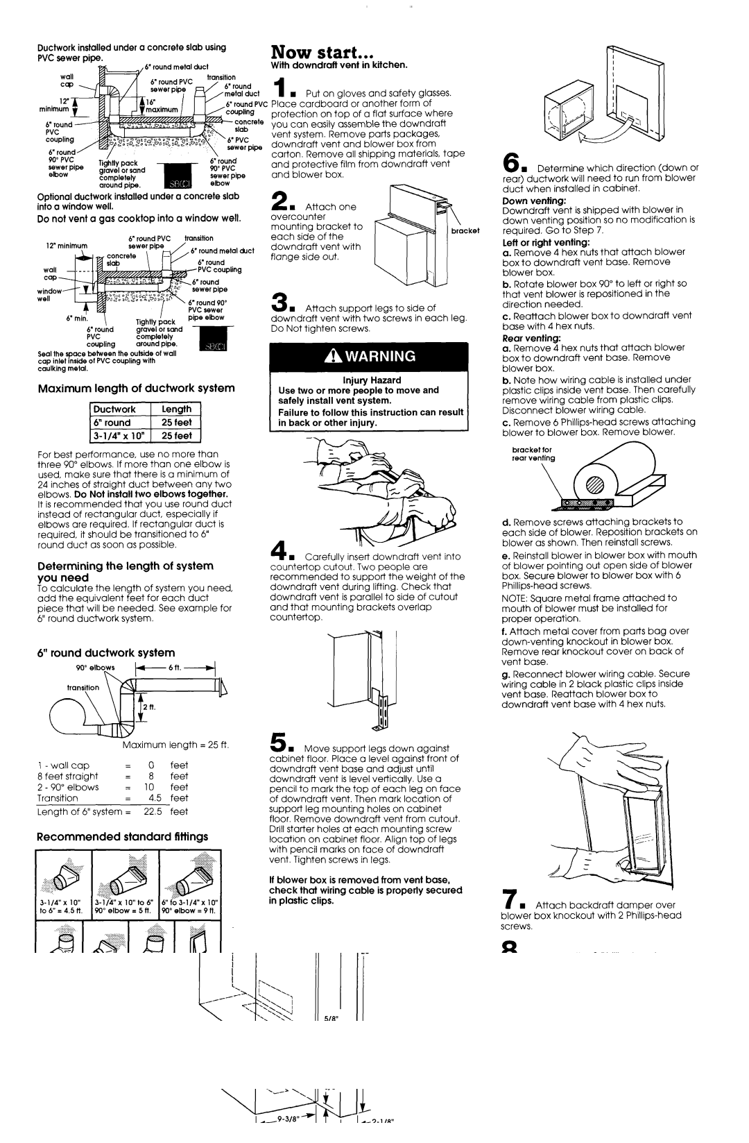
Ductwork installed under a concrete slab using PVC sewer pipe.

Optional ductwork installed under a concrete slab into a window well.

Do not vent a gas cooktop into a window well,

6”

round

PVC

transition

12” minimum


6” round metal duct

concreie


6” round

slab


T


I

PVC sewer

6” min.

Tiahtlv

pipe elbow


oock


6” rouhd

‘-G----I

r --.-


gravel

or sand


PVC

completely


coupling

around

pipe.


Seal the space between the outside of wall cap inlet inside of PVC coupling with caulking metal.

Maximum length of ductwork system

For best performance, use no more than three 90” elbows. If more than one elbow is used, make sure that there is a minimum of 24 inches of straight duct between any two elbows. Do Not install two elbows together.

It is recommended that you use round duct instead of rectangular duct, especially if elbows are required. If rectangular duct is required, it should be transitioned to 6” round duct as soon as possible.

Determining the length of system you need

To calculate the length of system you need, add the equivalent feet for each duct piece that will be needed. See example for 6” round ductwork system.

Now start...

With downdraft vent in kitchen.

1 n Put on gloves and safety glasses. Place cardboard or another form of protection on top of a flat surface where you can easily assemble the downdraft vent system. Remove parts packages, downdraft vent and blower box from carton. Remove all shippina materials, tape and protective film fro’& downdraft vent and blower box.

2 w Attach one overcounter

mounting bracket to each side of the downdraft vent with flange side out.

3 w Attach supper? legs to side of downdraft vent with two screws in each leg. Do Not tighten screws.

Injury Hazard

Use two or more people to move and safely install vent system.

Failure to follow this instruction can result in back or other injury.

4 w Carefullv insert downdraft vent into countertop cut&t. Two people are

recommended to support the weight of the downdraft vent during lifting. Check that downdraft vent is parallel to side of cutout and that mounting brackets overlap countertop.

6 H Determine which direction (down or rear) ductwork will need to run from blower duct when installed in cabinet.

Down venting:

Downdraft vent is shipped with blower in down venting position so no modification is required. Go to Step 7.

left or right venting:

a. Remove 4 hex nuts that attach blower box to downdraft vent base. Remove blower box.

b. Rotate blower box 90” to left or right so that vent blower is repositioned in the direction needed.

c. Reattach blower box to downdraft vent base with 4 hex nuts.

Rear venting:

a. Remove 4 hex nuts that attach blower box to downdraft vent base. Remove blower box.

b. Note how wiring cable is installed under plastic clips inside vent base. Then carefully remove wiring cable from plastic clips.

Disconnect blower wiring cable.

c. Remove 6 Phillips-head screws attaching blower to blower box. Remove blower.

bracket for real venting

\

d. Remove screws attaching brackets to each side of blower. Reposition brackets on blower as shown. Then reinstall screws.

e. Reinstall blower in blower box with mouth of blower pointing out open side of blower box. Secure blower to blower box with 6 Phillips-head screws.

NOTE: Square metal frame attached to mouth of blower must be installed for proper operation.

f. Attach metal cover from parts bag over

6” round ductwork system

6ft.-4

lb


Maximum length = 25 ft.

w Move support legs down against


I-wallcap


=

0

feet

cabinet

floor. PI&e

a

le;el against-front

of


downdraft

vent base and adjust until


8 feet

straight

=

8

feet


downdraft

vent

is level

vertically. Use a

2 - 90”

elbows

=

10

feet

pencil

to mark

the top

of

each

leg

on

face

Transition


=

4.5

feet

of downdraft

vent.

Then

mark

location

of

Length

of

6” system

=

22.5

feet

support

leg

mounting


holes on

cabinet


floor. Remove downdraft vent from cutout.

Recommended

standard

fittings

Drill starter holes at each mounting screw

location

on

cabinet

floor.

Align

top

of

legs


..

--.-


:i::

:::::::;..-.-.-.-..-...

vent.

Tighten

screws

in legs.


with pencil marks on face of downdraft


..i-I~~~~~~


...~~~:-.

If blower

box is removed

from

vent

base,

.::..-:::..:>.:::;


check

that

wiring cable

is properly

secured

3-l/&x

10”

3-l/$x

lO”to6”

6”f;63-1/4”xlo”

in plastic

clips.


to 6” = 4.5 ft.

90” elbow

=

5 ft.

90” elbow = 9 ft.


PO; ;,lbow

down-venting knockout in blower box. Remove rear knockout cover on back of vent base.

g. Reconnect blower wiring cable. Secure wiring cable in 2 black plastic clips inside vent base. Reattach blower box to downdraft vent base with 4 hex nuts.

7 w Attach backdraft damper over blower box knockout with 2 Phillips-head screws.

8 n Remove the 2 Phillips-head screws attaching appliance wirini box cover. Determine which direction (rear or down) electrical connection will need to run from appliance wiring box. Knock out rear or lower wiring opening in wiring box.

Panel C

Page 4
Image 4
Whirlpool 4.32E+13 installation instructions Now start, ~~~~~~

4.32E+13 specifications

The Whirlpool 4.32E+13 is a prominent model in the realm of home appliances, garnering attention for its innovative features, advanced technologies, and user-friendly design. Designed to streamline household chores, this model exemplifies Whirlpool's commitment to quality and performance.

One of the standout features of the Whirlpool 4.32E+13 is its energy efficiency. Equipped with Energy Star certification, this appliance consumes significantly less energy compared to traditional models, helping homeowners reduce their utility bills while minimizing their carbon footprint. This makes it an environmentally friendly option that aligns with modern sustainability practices.

The capacity of the Whirlpool 4.32E+13 is another highlight, offering ample space to accommodate large loads. This feature caters to families and individuals with busy lifestyles, ensuring that laundry can be completed efficiently and effectively. Whether it's washing bedding, towels, or everyday clothing, this appliance handles it all with ease.

Technologically, the Whirlpool 4.32E+13 is designed with smart features that enhance user convenience. Its intuitive control panel allows users to select wash cycles and customize settings with just a few taps. Additionally, the inclusion of sensor technology ensures that the appliance automatically adjusts water levels and cycle times based on the load size and fabric type. This results in optimal cleaning performance while conserving resources.

Another notable characteristic of the Whirlpool 4.32E+13 is its quiet operation. Engineered with sound-dampening technology, this model minimizes noise during use, making it suitable for homes where noise can be a concern. Users can run their laundry without disruption, even during nighttime hours.

Durability is a key aspect of the Whirlpool brand, and the 4.32E+13 exemplifies this with its robust construction and high-quality materials. This model is designed to last, providing reliable performance over the years.

In summary, the Whirlpool 4.32E+13 stands out in the world of home appliances with its energy efficiency, large capacity, smart features, quiet operation, and durability. It represents the blend of advanced technology and user-friendly design, making it an excellent addition to any household looking to simplify and enhance their laundry experience. With Whirlpool’s reputation for quality, consumers can trust that this model will deliver consistent and satisfying results.