INSTALLATION INSTRUCTIONS
Installer: Leave Use and Care Guide with the homeowner.
Homeowner: Keep Use & Care Guide for future reference and for local electrical inspector’s use, if required.
Tools and Parts
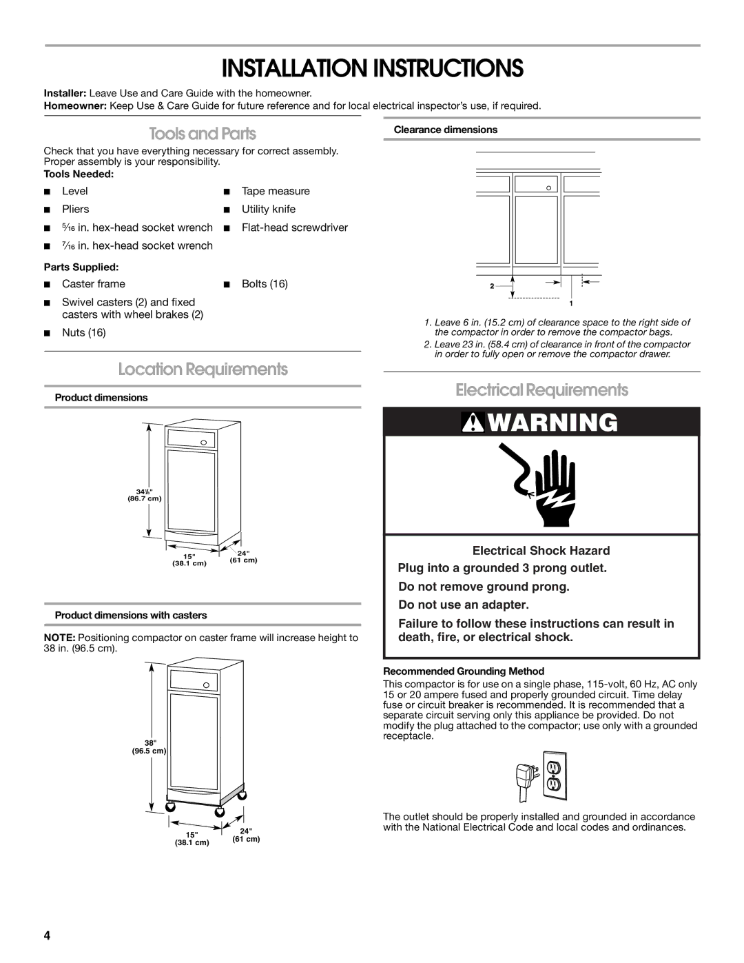
Clearance dimensions
Check that you have everything necessary for correct assembly. Proper assembly is your responsibility.
Tools Needed:
■ | Level | ■ | Tape measure |
■ | Pliers | ■ | Utility knife |
■ ⁵⁄₁₆ in. | ■ | ||
■⁷⁄₁₆ in.
Parts Supplied:
■ Caster frame | ■ Bolts (16) |
■Swivel casters (2) and fixed casters with wheel brakes (2)
■Nuts (16)
Location Requirements
Product dimensions
341/8"
(86.7 cm)
15" | 24" | |
(61 cm) | ||
(38.1 cm) | ||
|
Product dimensions with casters
NOTE: Positioning compactor on caster frame will increase height to 38 in. (96.5 cm).
38"
(96.5 cm)
15" | 24" | |
(61 cm) | ||
(38.1 cm) | ||
|
1.Leave 6 in. (15.2 cm) of clearance space to the right side of the compactor in order to remove the compactor bags.
2.Leave 23 in. (58.4 cm) of clearance in front of the compactor in order to fully open or remove the compactor drawer.
Electrical Requirements
![]() WARNING
WARNING
Electrical Shock Hazard
Plug into a grounded 3 prong outlet.
Do not remove ground prong.
Do not use an adapter.
Failure to follow these instructions can result in death, fire, or electrical shock.
Recommended Grounding Method
This compactor is for use on a single phase,
The outlet should be properly installed and grounded in accordance with the National Electrical Code and local codes and ordinances.
4