Manuals
/
Whirlpool
/
Kitchen Appliance
/
Dishwasher
Whirlpool
MAH3000
service manual
Machine Control, Board Output Test
Models:
MAH3000
1
142
157
157
Download
157 pages
41.3 Kb
139
140
141
142
143
144
145
146
Troubleshooting
Specs
Display Characteristics
Install
Code list
Electrical Schematics
End-Of-Cycle Signal Input
Timer Inputs
Wire Colors
Diagnostic
Page 142
Image 142
Page 141
Page 143
Page 142
Image 142
Page 141
Page 143
Contents
Washer
Service Manual
Customer Service
16010061
SAFETY PRECAUTIONS
USE ONLY GENUINE MAYTAG APPROVED FACTORY REPLACEMENT COMPONENTS
Models covered in this manual
INTRODUCTION
MAH3000
Maytag Appliances Sales Company 240 Edwards Street, S.E Cleveland, TN
C O N T E N T S
GENERAL
CABINET ASSEMBLY
SECTION
ASSEMBLY
DIAGNOSTIC
OUTER
MOTOR
Displacement
MACHINE
UNCRATING INSTRUCTIONS
PRE-INSTALLATION REQUIREMENTS
Checkpoints for proper installation
NOTE Proper installation is the responsibil- ity of the purchaser
INSTALLATION
GROUNDING POLARITY CHECKS
CAUTION Do not cut or remove the ground- ing prong from this plug
SPECIFICATIONS
USE OF ADAPTERS IS NOT RECOMMENDED
WASHER CONTROLS
Prior To Series
DOOR LOCK SWITCH INPUT
INPUT DEFINITIONS
Series 17 & Later
END-OF-CYCLE SIGNAL INPUT
START/STOP INPUT
TIMER INPUTS
Definitions
See Push-To-Start/Line Relay Operation
See Timer Input Charts
OUTPUT DEFINITIONS
END-OF-CYCLE SIGNAL OUTPUT
TIMER MOTOR OUTPUT
Vcc REFERENCE VOLTAGE OUTPUT
TORQUE OUTPUT
WATER VALVE OUTPUTS
Timer Motor Output and Section 2 Timer Input Chart
CYCLE SEQUENCE DEFINITIONS
1-10
BLEACH DISPENSE
Redistribution
MISCELLANEOUS Door Latch Switch Monitoring
Door Lock/Spin Control
1-11
STARTING THE WASHER
Push-To-Start Relay Operation
1-12
STOPPING THE WASHER
1-13
CYCLE REVIEW
Main Wash Time/Total Cycle Time - Minutes See Notes
Diagnosis - Clothes Wet at End of Spin
GENERAL COMPONENT EXPLODED VIEW
1-14
Description
SECTION 2. ELECTRICAL COMPONENTS & TESTING
ELECTRICAL TEST EQUIPMENT
Part Number
Voltage Checks
ELECTRICAL TESTS
G r o u n d e d C o m p o n e n t s
Water Valve Test
SECTION 2. ELECTRICAL COMPONENTS & TESTING
Timer & Console Switches
Timer Input Charts
T C B
1= Input
Key 0 = Input Signal
Not Asserted
t i m e r
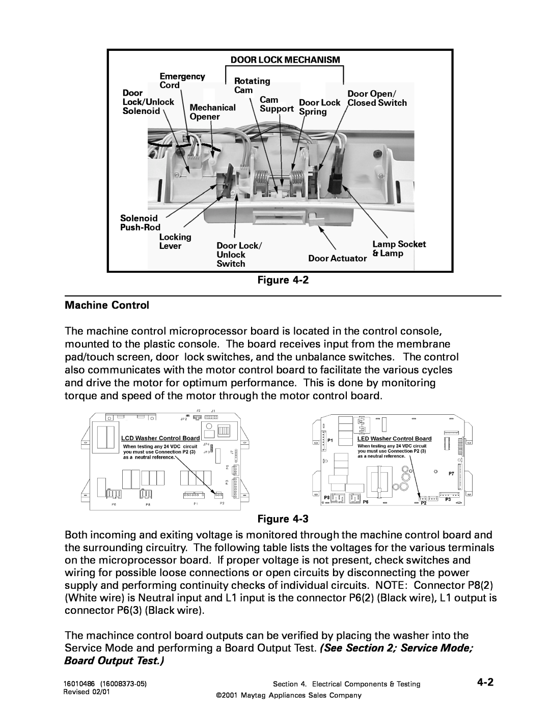
Machine Control
M A C HIN E
MOTOR CONTROL BOARD
DRIVE MOTOR
Motor Harness Connector
Motor Phase Test
Motor & Motor Control Test
1 . Disconnect power to the unit
Motor Windings Check
1 . Disconnect power to the washer prior to testing
w i n d i n g s c h e c k S e e M o t o r W i n d i n g s C h e c k
WIRE COLORS
Tachometer Circuit Diagnostics
PHASE
RESULT/SOLUTION
Tachometer
UNBALANCE CONTROL SYSTEM
Wire Checks
Voltage Found
Testing the Tub Displacement Switch 1 . Disconnect power to the unit
Tub Displacement Switch
Strut Displacement Switch
Testing the Strut Displacement Switch
Cabinet Vibration Sensor
Inertial Unbalance Switch
Cabinet Vibration Absorber
Testing the Inertial Unbalance Switch
1998 Maytag Corporation
Start Line Relay Operation
SECTION 3. TROUBLESHOOTING
Shuts OFF When Push-To-Start Button Re- leased
Runs For Five Seconds Then Shuts OFF
Third Rinse Cycle Is Always Cold
Tumbles Only
ContinuesTo Tumble After The Wash Cycle Is Finished
Temperature Inputs
Ticking or Knocking Noise In Spin
Door Leaks
“Thumping” Noise In Spin
RF Radio Frequency Interference
T R O U B L E S H O O T I N G
SECTION 3. TROUBLESHOOTING 3
1998 Maytag Corporation
T R O U B L E S H O O T I N G
SECTION 3. TROUBLESHOOTING
1 6 0 0 8 3 7 3
1998 Maytag Corporation
T R O U B L E S H O O T I N G
SECTION 3. TROUBLESHOOTING 3
1 6 0 0 8 3 7 3 - 0
1998 Maytag Corporation
T R O U B L E S H O O T I N G
SECTION 3. TROUBLESHOOTING
1 6 0 0 8 3 7 3 - 0
1998 Maytag Corporation
3 - 1
SECTION 3. TROUBLESHOOTING 3 - 1
3 - 1
indicators of the Quick Wash and Regular wash
SECTION 3. TROUBLESHOOTING 3 - 1
Washer
MISCELLANEOUS INFORMATION
Energy Usage
Wattages
Disconnect power to the unit
SECTION 4. CONSOLE
R E M O V A L
HORIZONTAL SWITCHES Push-to-Start
VERTICAL SWITCHES Push Button
R E P L A C E M E N T
TIMER REMOVAL
SECTION 4. CONSOLE
DISASSEMBLY
SECTION 5. CABINET ASSEMBLY
DOOR ASSEMBLY & HINGES
R E M O V A L
FRONT PANEL
Cabinet Vibration Absorber
Door Latch Hoop
Disconnect power to the unit
DOOR LOCK MECHANISM
TOP COVER
1. Remove the front panel See Front Panel Removal
Troubleshooting
FRONT SHROUD ASSEMBLY
REMOVAL
See Front Panel & Top Cover
CABINET ASSEMBLY w/REAR ACCESS PANEL
Hinge Removal
1998 Maytag Corporation
REAR REMOVAL
SECTION 6. WATER-CARRYING COMPONENTS
WATER VALVE
FRONT REMOVAL
REMOVAL FROM CONSOLE
WATER LEVEL PRESSURE SWITCH
AIR DOME HOSE
REMOVAL FROM OUTER TUB
REPLACEMENT/ROUTING
DISPENSER ASSEMBLY
NOTE Using soap and water may lead to a potential leak
5. Disconnect the hoses attached to the dis- penser assembly
PUMP ASSEMBLY
FRONT WATER FLUME INJECTOR
procedure is not followed properly
1. Depress the locking tab on the face of the pump housing
Pump Accessory Kit
CLEANING THE PUMP
7. Installation is complete
DRAIN HOSE
5. Reverse the previous steps for replacement
SECTION 6. WATER CARRYING COMPONENTS
SECTION 7. OUTER TUB & SPINNER ASSEMBLY
DOOR BOOT
BAFFLES
Front Shroud Removal
2. Stretch the rear lip of the door boot onto the tub cover
OUTER TUB COVER
REPLACEMENT
Shroud
SPIN BASKET ASSEMBLY w/BALANCE RING
1. Slide pulley on shaft
DRIVE PULLEY
Figure7-6
Profile Washer Spinner Support Washer Locking Nut
7. Remove the shaft seal Figure
SPINNER TUB SUPPORT
3. Remove the drive pulley See Pulley Removal
1. Reverse the previous steps
SEAL SYSTEM
Figure7-9
BEARINGS
OUTER TUB ASSEMBLY
COUNTER WEIGHTS
REMOVAL OF UPPER WEIGHT 1. Disconnect power to the unit
INERTIAL UNBALANCE SWITCH
STRUT ASSEMBLY
Strut Displacement Switch
3. Remove the wires to the switch
TUB DISPLACEMENT SWITCH
1998 Maytag Corporation
DRIVE MOTOR
SECTION 8. MOTOR DRIVE SYSTEM
DRIVE BELT
R E M O V A L
MACHINE CONTROL
Console Removal
MOTOR CONTROL
R e m o v a l
1998 Maytag Corporation
ELECTRICAL SCHEMATICS
SECTION 9. ELECTRICAL SCHEMATICS & TIMER I N F O R M A T I O N
Prior to Series
SECTION
TIMER CHART - Prior to Series
ELECTRICAL SCHEMATIC - Series
TIMER CHART - Series
SECTION
ELECTRICAL SCHEMATIC - Series
ELECTRICAL SCHEMATICS
1998 Maytag Corporation
SECTION
TIMER CHART - Series
ELECTRICAL SCHEMATICS
1998 Maytag Corporation
SECTION
N O T E S
DISPENSER ASSEMBLY
CONTENTS
SPECIFICATIONS
WIRING INFORMATION
SECTION 1. MAH4000/MAH5500A CONTROL FACIA SECTION 2. SPECIFICATIONS
Series 10 MAH4000 only
SECTION 3. BASIC MACHINE OPERATION
SECTION 4. WASHER CONTROLS OVERVIEW
Series 11 & Later
SECTION 5. CYCLE REVIEW
Non-Max
Cycle Times
All Wash Time/Total Wash Cycle
Cotton/Sturdy
The following is an example of a Stain Cycle
Stain Cycle
General overview of Stain Cycle
Suds detection during stain cycle
SECTION 6. GENERAL COMPONENT - EXPLODED VIEW
Component Identification & Location
SECTION 7. ELECTRICAL INFORMATION
1. Discontinue power and water to the
electrical power to the unit
vice repair procedures
SECTION 8. WATER CARRYING COMPONENTS
OPERATION
1. Disconnect power and water to the machine
See Figure
Removal 1. Disconnect power and water to the washer
NOTE Indicator mark on hose for reinstallation
See Figure 8-11
3. Locate the rear mounting clip on the detergent hose in the access panel opening and slide the clip off the cabinet flange. See Figure
Page
SECTION 9. WIRING INFORMATION
SERIES 10 - SCHEMATIC MAH4000 only
SERIES 11 MAH4000 and MAH5500
SERIES 10 - TIMER CHART MAH4000
SERIES 11 - TIMER CHART MAH4000 & MAH5500A
16008373-05
New Century Neptune Washer Service Manual Supplement
MAYTAG
TEARDOWN & WIRING INFORMATION
DIAGNOSTIC/HELP CODE TABELS
SECTION 4. ELECTRICAL COMPONENTS & TESTING
Models covered in this manual supplement MAH5500B MAH7500A
Revised 02/01
MAH5500B CONTROL FACIA
SPECIFICATIONS
SECTION 1. GENERAL INFORMATION
MAH7500 CONTROL FACIA
General Flow Of A Complete Wash Cycle
BASIC MACHINE OPERATION
Wash Selections
CYCLE SEQUENCES
Wash Time Tumble
Tumbling Time
Selected
INPUT WATER TEMPERATURE
Extra Heavy, Quick
Rinse
SECTION 2. WASHER CONTROLS OVERVIEW
Features of MAH5500B LED Washer
Features of MAH7500 LCD Washer
BASIC CONTROL BOARD PHILOSOPHY FOR BOTH WASHERS
SELECTIONS LED Washer
SIGNAL MODE
USER INTERFACE
FABRIC MODE
Page 1-3 Extra Rinse Table
DISPLAY CHARACTERISTICS
OPTIONS MODE
Door Locked LED
INPUT MODIFICATIONS DEFINED
PRESSURE SWITCH INPUT
DOOR LOCK SWITCH INPUT
TEMPERATURE SENSOR INPUT
START/PAUSE INPUT
Diagnostics
OUTPUT MODIFICATIONS DEFINED
TACH INPUT
Main Wash Target Temperatures
CYCLE SEQUENCE DEFINITIONS
WATER VALVE OUTPUTS
REDISTRIBUTION
BLEACH DISPENSE
SUDS DETECTION
DOOR LOCK PHILOSOPHY
MISCELLANEOUS
DOOR LOCK OPERATION
MAH7500A
POWER LOSS/FAILURE
SPECIAL FEATURES
ADVERTISING MODE
LCD Washer
SERVICE MODE
LED Washer
2-10
LED WASHER
Accessing Service Mode
SERVICE MODE TABLE LED Washer
SPECIAL TESTS
Speed Range
QUICK SERVICE CYCLE
2-12
Displayed
HELP CODES
Accessing The Help Codes
BOARD INPUT TEST
BOARD OUTPUT TEST
Accessing Diagnostic Codes
DIAGNOSTIC CODES
Section 5 DIAGNOSTIC/HELP CODE TABLES
Clearing Diagnostic Code List
LCD WASHER
ACCESSING SERVICE MODE
Service Tests
User Interface Tests
During a cycle
Service Cycle
2-16
Note This selection is valid only if a cycle is running
2-17
Clear diagnostic codes Clear the entire list of diagnostic codes
DIAGNOSTIC/HELP CODES
exit diagnostic/help codes Return to
SYSTEM CHECK
Help
Section 3 DIAGNOSTIC/HELP CODE TABLES
HELP CODES LISTING
Trigger
Trigger
Help
Description
Action to be Taken
Trigger
Description
DIAGNOSTIC CODES LISTING
Diag
Trigger
Diag
Trigger
GENERAL COMPONENT - EXPLODED VIEW
Component Identification & Location
Glossary of Terms
Spin Speed - This is the speed of the washer spinner during extraction
3-10
Grounded Components
SECTION 4. ELECTRICAL COMPONENTS & TESTING
ELECTRICAL TESTS
Water Valve Test
Machine Control
Board Output Test
INPUT/OUTPUT VOLTAGES LCD Washer
INPUT/OUTPUT VOLTAGES LED Washer
Membrane Pad Checks
On the MAH5500B washer you can perform the Membrane Pad Check with the control console. See Section 2 Accessing Service Mode Membrane Pad Check
MOTOR CONTROL BOARD
Motor Control Access
DRIVE MOTOR
Drip Shield Removal
Machine Control Board Output Test
Motor Phases
Motor Drive System Test
Motor & Motor Control Test
HEATER ASSEMBLY
Heater Will Not Turn On
User Selections
Thermistor Temperature Chart
Heating Targets Using
Main Wash Tempering
MICROPROCESSOR BOARD REMOVAL
SECTION 5. TEARDOWN & WIRING INFORMATION
CONSOLE REMOVAL
LCD MODEL
CONSOLE COVER PLUG
CABINET ASSEMBLY
DOOR LATCH HOOP
DOOR LOCK MECHANISM
PRESSURE SWITCH
REAR ACCESS PANEL
Removal 1. Discontinue power and water to the machine
WATER SYSTEM COMPONENTS
REINSTALLATION
PUMP ASSEMBLY
HEATER ASSEMBLY
REMOVAL
Thermistor Removal
SUMP COVER
WIRING INFORMATION
MAH5500B
MAH7500
Customer Service 240 Edwards Street, S.E Cleveland, Tennessee
Maytag Appliances Sales Company
Top
Page
Image
Contents