Cony. from Panel A
revxed The appliance coblnet must not be connected to the neutral termlnol. but must be connected to the grounding we [green] of the power supply cord. [See
When o
The MINIMUM conductor sizes for the copper
50 ampere circuit
2.NO.6 conductors
1.No 8 white neutral
1.No 6 green groundtng
A wiring diagram ISincluded H in the lech sheet. The tech sheet IS
‘located behtnd the control panel
Venting requhements
Terminate venting system to the
Do Not terminate the vent in an attic or other enclosed space.
Failure to follow these instructions could result in a fire.
Ductwork needed for lnslallafion is not included. Wall or roofcaps used must have
Determine which outslde venting
method needs to be used Note: If a non- venting (reclrculatlng] Installation 1s desired, you will need to order
The length of ductwork and number of elbows should be kept to a mlnimum to provide effictent performance The size of the ductwork should be uniform Do Net install two elbows together Use duct tape to seal all joints In duct system. Ductwork can terminate either through the roof or wall. Figures
Figure 4
3.” x to 3Y4”x 10” through the roe, through wall
3Y.” | I lo- to |
|
rouna | duct | 3Y.” x to” to round |
lransitlon | ductwork transitlon | |
Recommended duct length
Use 3b” x VY or & duct with a maxImum length of 26 feet for duct system For bes’ perlormance use no more than
PANlt 8
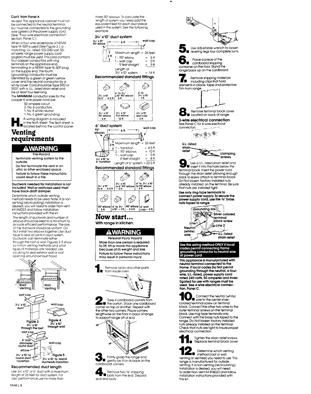
three 90” elbows To calculate the length of system you need add the equivalent feet for each duct piece used In the system See the following example
3W x IO” duct system
| 9 feet straight | = | 9n |
Length of |
|
| |
Wi’ | x 10” system | = | i4n |
Recommended | standard | fiitlngs | |
, |
| 1 | |
6” duct | system | wall cap | |
90” | |||
, |
Lenath of 6” svstem = 22.5 ft
Now start...
With range in kitchen.
I Personal lniuw Hazard
More than one p&on is required to lifi. tilt or move this aoollance because of Its weight did size.
Failure to follow these instructions may result in personal injury.
1 Remove racks and other parts n from Inside oven.
2 Take 4 cardboard corners from n the carton. Stack one cardbcard
corner on tap of another. Repeat with the other two comers. Place corners lengthwise on the floor in back of range to support range off of skid.
3 Ftrmly grasp the range and w Rentlv lay it on Its back on the
cardboard corners
4 Remove two Vu” shipping n bolts from the skid Discard
skid and bolts
5 Use adJustable wrench to loosen n leveling legs four complete turns.
6 Place a piece of the n cardboard shipping
container on the floor. Stand the range buck up on the cardboard
7 Remove shipping materials w including clips that hold
elements in place, tape and protective film from rangem
Remove terminal block cover n located on back of range
J-wire electrical connectlon
See Panel C for
connection.
9 Use a U L
terminal block. Insert the power cord through the strain relief allowing enough slack to easily attach to terminal block. Do Not loosen
Use onlv
$;Sllver.colored
This appliance Is manufactured wlth neutral terminal connected to the frame. If local codes Do Not permll graundlng through the neutral. a tour- wire.
10 Connect the neutral [white] n wire to the center silver-
colored terminal screw on terminal
block. Connect the other two wires to the outer terminal screws on the terminal block. Use
11 Tighten the strain relief screws.
. Replace terminal block cover.
12 Determine which venting n method (roof or wall
venting orventless) you need to use This range is manufactured for outslde venting. If a
to order