Service Diagnostics Mode (continued)
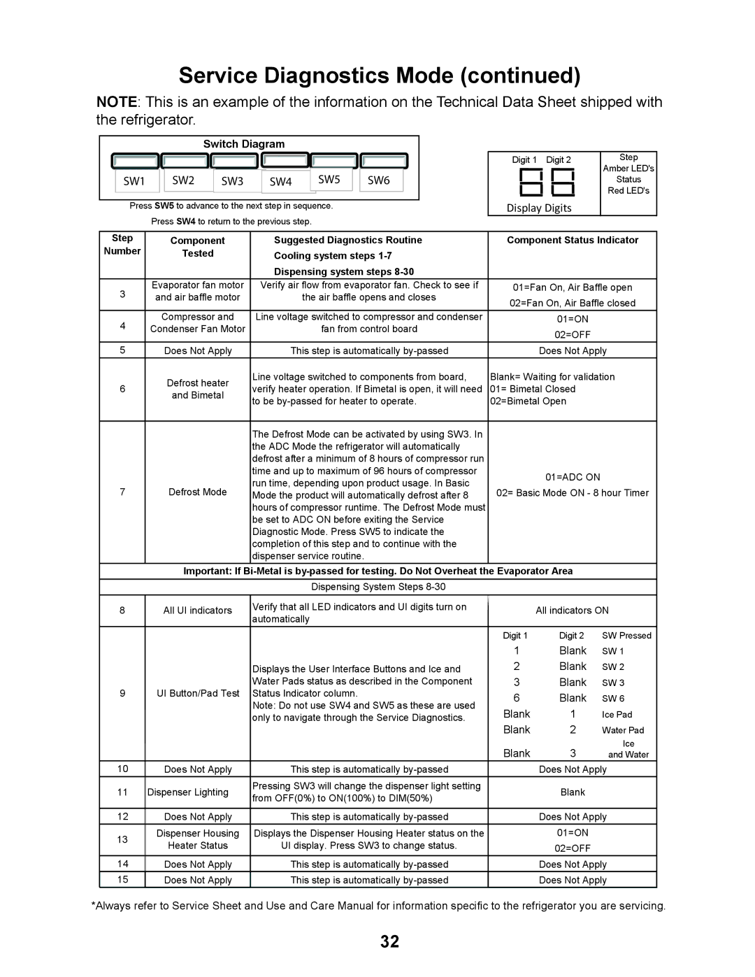
NOTE: This is an example of the information on the Technical Data Sheet shipped with the refrigerator.
|
| Switch Diagram |
|
| |
SW1 | SW2 | SW3 | SW4 | SW5 | SW6 |
Press SW5 to advance to the next step in sequence.
Press SW4 to return to the previous step.
Digit 1 Digit 2
Display Digits
Step
Amber LED's
Status
Red LED's
Step | Component | Suggested Diagnostics Routine | Component Status Indicator | ||||
Number | Tested | Cooling system steps |
|
|
| ||
|
| Dispensing system steps |
|
|
| ||
3 | Evaporator fan motor | Verify air flow from evaporator fan. Check to see if | 01=Fan On, Air Baffle open | ||||
and air baffle motor | the air baffle opens and closes | 02=Fan On, Air Baffle closed | |||||
|
|
|
| ||||
4 | Compressor and | Line voltage switched to compressor and condenser |
| 01=ON |
| ||
Condenser Fan Motor | fan from control board |
| 02=OFF |
| |||
|
|
|
|
|
| ||
5 | Does Not Apply | This step is automatically |
| Does Not Apply | |||
| Defrost heater | Line voltage switched to components from board, | Blank= Waiting for validation | ||||
6 | verify heater operation. If Bimetal is open, it will need | 01= Bimetal Closed |
| ||||
and Bimetal |
| ||||||
| to be | 02=Bimetal Open |
| ||||
|
|
| |||||
|
|
|
|
|
|
| |
|
| The Defrost Mode can be activated by using SW3. In |
|
|
| ||
|
| the ADC Mode the refrigerator will automatically |
|
|
| ||
|
| defrost after a minimum of 8 hours of compressor run |
|
|
| ||
|
| time and up to maximum of 96 hours of compressor |
| 01=ADC ON |
| ||
|
| run time, depending upon product usage. In Basic |
|
| |||
7 | Defrost Mode | 02= Basic Mode ON - 8 hour Timer | |||||
Mode the product will automatically defrost after 8 | |||||||
|
| hours of compressor runtime. The Defrost Mode must |
|
|
| ||
|
| be set to ADC ON before exiting the Service |
|
|
| ||
|
| Diagnostic Mode. Press SW5 to indicate the |
|
|
| ||
|
| completion of this step and to continue with the |
|
|
| ||
|
| dispenser service routine. |
|
|
| ||
| Important: If |
| |||||
|
| Dispensing System Steps |
|
|
| ||
|
|
|
|
|
|
| |
8 | All UI indicators | Verify that all LED indicators and UI digits turn on |
| All indicators ON | |||
automatically |
| ||||||
|
|
|
|
| |||
|
|
|
| Digit 1 | Digit 2 | SW Pressed | |
|
|
|
| 1 | Blank | SW 1 | |
|
| Displays the User Interface Buttons and Ice and | 2 | Blank | SW 2 | ||
|
| Water Pads status as described in the Component | 3 | Blank | SW 3 | ||
9 | UI Button/Pad Test | Status Indicator column. | 6 | Blank | SW 6 | ||
|
| Note: Do not use SW4 and SW5 as these are used | |||||
|
| Blank | 1 | Ice Pad | |||
|
| only to navigate through the Service Diagnostics. | |||||
|
|
|
| Blank | 2 | Water Pad | |
|
|
|
| Blank | 3 | Ice | |
|
|
|
| and Water | |||
10 | Does Not Apply | This step is automatically |
| Does Not Apply | |||
11 | Dispenser Lighting | Pressing SW3 will change the dispenser light setting |
| Blank |
| ||
from OFF(0%) to ON(100%) to DIM(50%) |
|
| |||||
|
|
|
|
| |||
|
|
|
|
|
| ||
12 | Does Not Apply | This step is automatically |
| Does Not Apply | |||
13 | Dispenser Housing | Displays the Dispenser Housing Heater status on the |
| 01=ON |
| ||
Heater Status | UI display. Press SW3 to change status. |
| 02=OFF |
| |||
|
|
| |||||
14 | Does Not Apply | This step is automatically |
| Does Not Apply | |||
15 | Does Not Apply | This step is automatically |
|
| Does Not Apply | ||
*Always refer to Service Sheet and Use and Care Manual for information specific to the refrigerator you are servicing.
32