Product Damage
DO NOT connect to a hot water supply line.
Failure to follow this instruction could result in product damage.
la Take note of water requirements listed under
. the Use & Care section of this booklet. The filtration system’s feed line (orange tubing) connects to your cold water supply line using the saddle valve.
Do not use saddle valve if it is prohibited by your state or local plumbing codes.
The saddle valve is for use with 3/s” to s/B”outer diameter (O.D.), soft copper pipe (plain or chrome plated) or rigid metal or plastic pipe. Important: DO NOT use the saddle valve on flexible ribbed tubing. The wall thickness of flexible ribbed tubing is thin and will not support the saddle valve supplied.
If your cold water supply is connected to the cold water faucet with flexible ribbed tubing, contact your local plumbing supply distributor to obtain special connecting hardware.
Important: If local codes do not permit the use of saddle valves, special feed valves can be obtained from your local plumbing supply distribu- tor. Use only W’ polyethylene tubing for water line
connection.- - - -
Property/Product Damage
l DO NOT install tubing in an area where temperatures drop below 32°F.
l DO NOT overtighten saddle valve to copper pipe. This will crush pipe.
l Keep a bucket or towel under area where saddle valve connection is made.
Failure to follow these instructions may result in water damage to property or product damage.
lb Turn off cold water SUDDIV. Turn on cold
. water faucet and allow all water to drain from line. Turn off faucet. Determine if your cold water sup- ply line is soft copper pipe or rigid metal or plastic pipe. If your cold water supply line is soft copper pipe, pro- ceed to step 1c. If your cold water supply line is
rigid metal or plastic pipe, skip ahead to step 1h.
|
|
|
|
|
|
|
|
|
|
|
|
|
|
|
|
|
| j | i |
|
|
|
|
|
|
|
|
|
|
|
|
|
|
|
|
|
|
|
|
|
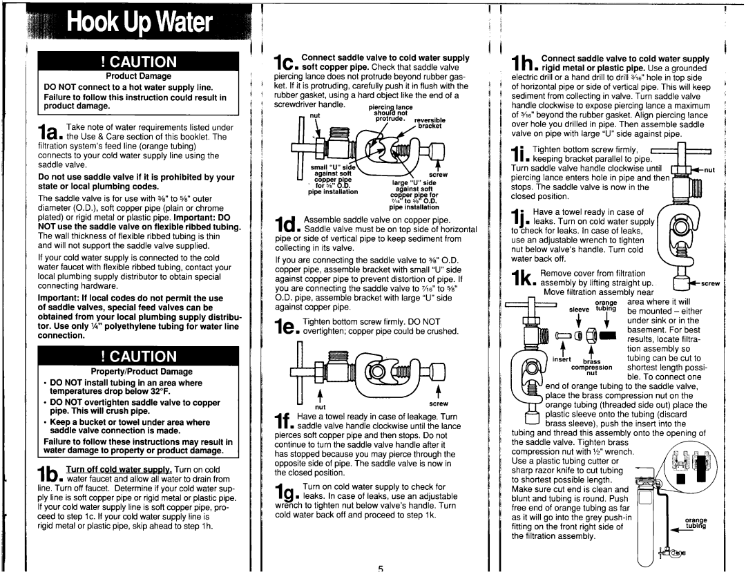
Ic . | Connect |
| saddle | valve | to | cold | water | supply | 1 li* | Ih |
| Connect | saddle |
| valve | to | cold | water | 5 | |||||||||||||||||||||
|
|
|
|
| supply | |||||||||||||||||||||||||||||||||||
soft copper | pipe. | Check | that | saddle | valve |
|
| . | rigid | metal | or | plastic | pipe. | Use | a grounded | |||||||||||||||||||||||||
piercing | lance does not | protrude | beyond | rubber gas- |
|
| electric | drill | or a hand | drill | to drill 3h6” | hole | in top side | |||||||||||||||||||||||||||
ket. If it is protruding, | carefully | push | it in flush | with the | i | c | of horizontal | pipe | or side | of vertical | pipe. | This will keep | ||||||||||||||||||||||||||||
rubber |
| gasket, | using | a hard object | like the end of a |
|
| sediment | from ‘collecting | in valve. Turn | saddle | valve | ||||||||||||||||||||||||||||
screwdriver | handle. |
|
|
|
|
|
|
|
|
|
|
|
|
|
| handle | clockwise | to expose | piercing | lance | a maximum | |||||||||||||||||||
|
|
|
|
|
|
|
|
|
|
|
|
|
|
|
|
|
|
|
| of %6” beyond the rubber gasket. Align piercing lance | ||||||||||||||||||||
|
|
|
|
|
|
|
|
|
|
|
|
|
|
|
|
|
|
|
| over hole you drilled in pipe. Then assemble saddle | ||||||||||||||||||||
|
|
|
|
|
|
|
|
|
|
|
|
|
|
|
|
|
|
|
| valve on pipe with large “U”side against pipe. |
| |||||||||||||||||||
|
|
|
|
|
|
|
|
|
|
|
|
|
|
|
|
|
|
|
| ’ |
| Tighten | bottom | screw | firmly, |
|
|
|
|
|
| |||||||||
|
|
|
|
|
|
|
|
|
|
|
|
|
|
|
|
|
|
|
| II . keeping bracket parallel to pipe |
|
|
|
| ||||||||||||||||
|
|
|
|
|
|
|
|
|
|
|
|
|
|
|
|
|
|
|
| Turn saddle valve handle clockwise until |
|
|
| |||||||||||||||||
|
|
|
|
|
|
|
|
|
|
|
|
|
|
|
|
|
|
|
| oiercina lance enters hole in pipe and then |
|
| ||||||||||||||||||
|
| pipe installation |
|
|
|
|
|
|
|
|
|
|
|
|
|
| stops. The saddle valve is now in the |
|
|
|
| |||||||||||||||||||
|
|
|
|
|
|
|
|
|
|
|
|
|
|
|
| closed |
| position. |
|
|
|
|
|
|
|
|
|
|
|
|
|
| ||||||||
|
|
|
|
|
|
|
|
|
|
|
|
|
|
|
|
|
|
|
|
|
|
|
|
|
|
|
|
|
|
|
|
|
|
| ||||||
|
|
|
|
|
|
|
|
|
|
| pipe | installation |
|
|
|
|
|
| Have | a towel | ready |
| in case | of |
|
|
|
| ||||||||||||
Id . | Assemble | saddle | valve | on copper | pipe. |
|
| n |
|
|
|
|
|
| ||||||||||||||||||||||||||
|
| 11 . | leaks. | Turn | on cold |
| water | supply |
|
|
|
| ||||||||||||||||||||||||||||
Saddle | valve |
| must be on top side of horizontal |
|
| to check | for | leaks. | In case | of leaks, |
|
|
|
|
| |||||||||||||||||||||||||
pipe or side of vertical | pipe to keep | sediment | from |
|
| use | an | adjustable | wrench |
| to tighten |
|
|
|
|
| ||||||||||||||||||||||||
collecting | in its valve. |
|
|
|
|
|
|
|
|
|
|
|
|
| nut | below | valve’s | handle. |
| Turn | cold |
|
|
|
|
| ||||||||||||||
If you | are | connecting |
| the | saddle | valve |
| to 3/e”O.D. |
|
| water | back | off. |
|
|
|
|
|
|
|
|
|
|
|
|
|
| |||||||||||||
copper pipe, assemble bracket with small “U”side |
|
| Ik . | Remove | cover | from filtration |
|
|
|
|
| |||||||||||||||||||||||||||||
against copper pipe to prevent distortion of pipe. If |
|
|
|
|
|
|
| |||||||||||||||||||||||||||||||||
|
| assembly | by | lifting | straight |
| up. |
|
|
| screw | |||||||||||||||||||||||||||||
you are connecting the saddle valve to %6” to W |
|
|
|
|
|
| ||||||||||||||||||||||||||||||||||
|
|
| _ |
| Move | filtration | assembly | near |
|
|
|
| ||||||||||||||||||||||||||||
O.D. pipe, | assemble |
| bracket | with | large | “U”side |
|
|
|
|
|
|
|
| ||||||||||||||||||||||||||
|
|
|
|
|
|
|
|
|
|
|
|
|
|
|
|
| area | wnere | it will | |||||||||||||||||||||
against | copper | pipe. |
|
|
|
|
|
|
|
|
|
|
|
|
|
|
|
|
|
|
|
| SkeVe |
|
|
|
|
| be | mounted | - | either | ||||||||
|
| Tighten bottom screw firmly. DO | NOT |
|
|
|
|
|
|
|
|
|
|
|
|
|
|
|
|
| under sink | or in the | ||||||||||||||||||
le . |
|
|
|
|
|
|
|
|
|
|
|
|
|
|
|
| basement. |
| For best | |||||||||||||||||||||
|
|
|
|
|
|
|
|
|
|
|
|
|
|
|
| results, | locate | filtra- | ||||||||||||||||||||||
|
|
|
|
|
|
|
|
|
|
|
|
|
|
|
|
|
|
|
|
|
|
|
|
|
|
|
|
|
|
|
|
|
| |||||||
|
|
|
|
|
|
|
|
|
|
|
|
|
|
|
|
|
|
|
|
|
|
|
|
|
|
|
|
|
|
|
|
|
| tion | assembly | so | ||||
|
|
|
|
|
|
|
|
|
|
|
|
|
|
|
|
|
|
|
|
|
|
|
|
|
|
|
|
|
|
|
|
|
| tubing can be cut to | ||||||
|
|
|
|
|
|
|
|
|
|
|
|
|
|
|
|
|
|
|
|
|
|
|
|
|
|
|
|
|
|
|
|
|
| shortest | length | possi- | ||||
|
|
|
|
|
|
|
|
|
|
|
|
|
|
|
|
|
|
|
|
|
|
|
|
|
|
|
|
|
|
|
|
|
| ble. To connect | one | |||||
|
|
|
|
|
|
|
|
|
|
|
|
|
|
|
|
|
|
|
|
|
|
|
| end of orange tubing to the saddle valve, | ||||||||||||||||
| Ll |
|
|
|
|
|
|
|
|
|
|
|
|
|
|
|
|
|
|
|
|
| place the brass compression nut on the | |||||||||||||||||
| nk |
|
|
|
|
|
|
|
|
|
|
| screw |
|
|
|
|
|
| orange | tubing | (threaded | side | out) place the | ||||||||||||||||
|
|
|
|
|
|
|
|
|
|
|
|
|
|
|
|
|
|
|
|
|
|
| plastic sleeve onto the tubing (discard | |||||||||||||||||
| Have a towel ready in case of leakage. Turn |
|
|
|
|
|
| |||||||||||||||||||||||||||||||||
If . saddle valve handle clockwise until the lance |
|
|
|
|
|
| brass sleeve), push the insert into the | |||||||||||||||||||||||||||||||||
|
| tubing and thread this assembly onto the opening of | ||||||||||||||||||||||||||||||||||||||
pierces soft copper pipe and then stops. Do not |
|
| ||||||||||||||||||||||||||||||||||||||
|
| the saddle valve. Tighten brass |
|
|
|
|
|
|
| |||||||||||||||||||||||||||||||
continue to turn the saddle valve handle after it |
|
|
|
|
|
|
|
|
| |||||||||||||||||||||||||||||||
|
| compression nut with %” wrench |
|
|
|
|
|
| ||||||||||||||||||||||||||||||||
has stopped because you may pierce through the |
|
|
|
|
|
|
|
| ||||||||||||||||||||||||||||||||
|
| Use a plastic tubing cutter or |
|
|
|
|
|
|
| |||||||||||||||||||||||||||||||
opposite side of pipe. The saddle valve is now in |
|
|
|
|
|
|
|
|
| |||||||||||||||||||||||||||||||
|
| sharp razor knife to cut tubing |
|
|
|
|
|
|
| |||||||||||||||||||||||||||||||
the closed | position. |
|
|
|
|
|
|
|
|
|
|
|
|
|
|
|
|
|
|
|
|
| ||||||||||||||||||
|
|
|
|
|
|
|
|
|
|
|
|
|
| to shortest | possible | length. |
|
|
|
|
|
|
|
| ||||||||||||||||
|
| Turn on cold | water | supply | to check | for |
|
|
|
|
|
|
|
|
|
| ||||||||||||||||||||||||
|
|
|
| Make | sure cut end is clean | and |
|
|
|
|
|
| ||||||||||||||||||||||||||||
Ig | . | leaks. | In case | of leaks, | use | an | adjustable |
|
| blunt | and | tubing | is round. | Push |
|
|
|
|
|
|
| |||||||||||||||||||
wrench | to tighten | nut | below | valve’s | handle. |
| Turn |
|
| free | end | of orange | tubing |
| as far |
|
|
|
|
|
| |||||||||||||||||||
cold water | back | off and | proceed | to step 1k. |
|
|
| as it will go into the grey |
|
|
|
|
| 3:; |
| |||||||||||||||||||||||||
|
|
|
|
|
|
|
|
|
|
|
|
|
|
|
|
|
|
|
| fitting | on the front right side of |
|
|
|
|
|
| |||||||||||||
|
|
|
|
|
|
|
|
|
|
|
|
|
|
|
|
|
|
|
| the | filtration | assembly. |
|
|
|
|
|
|
|
|
|
|
|
| ||||||
5